Deck 39: Regulated Power Supplies
Full screen (f)
Question
Question
Question
Question
Question
Question
Question
Question
Question
In Fig. 39-5, V in = 20 V, V Z = 4.7 , R 1 = 2.2 k , R 2 = 4.7 kV, R 3 = 1.5 k , R 4 = 2.7 k , and R L = 50 . What is the output voltage What is the power dissipation in the pass transistor 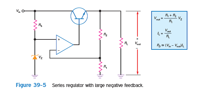
Question
Question
What is the approximate efficiency in Prob. 24-8 
Question
Question
In Fig. 39-7, the zener voltage is changed to 6.2 V. What is the approximate output voltage 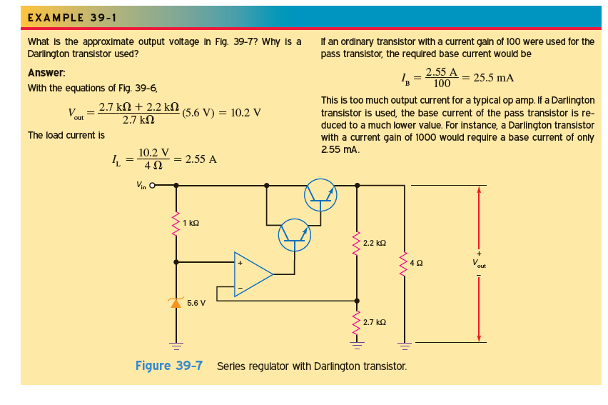
Question
Question
What is the load current in Fig. 39-31 The headroom voltage The power dissipation of theLM7815 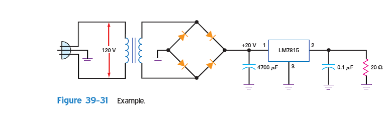
Question
Question
What is the output ripple in Fig. 39-31 
Question
Question
If R 1 = 2.7 k and R 2 = 20 k in Fig. 39-11, what is the output voltage 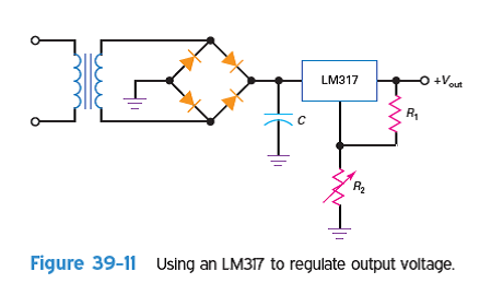
Question
Question
Question
Question
Question
Question
Question
Question
Question
Question
Question
Question
Question
Question
Question
Question
Question
Question
Question
Question
Question
Question
Question
Question
Question
Question
Question
Question
Question
Question
Question
Question
Question
Question
Question
Question
Question
Question
Question
Question
Question

Unlock Deck
Sign up to unlock the cards in this deck!
Unlock Deck
Unlock Deck
1/60
Play
Full screen (f)
Deck 39: Regulated Power Supplies
1
A power supply has V NL = 15 V and V FL =14.5 V. What is the load regulation
Write the expression for load regulation.  Here,
Here,  is the load voltage at no load current
  is the load voltage at full load current
Substitute 15 V for ,
, 
 and determine load regulation.
  Therefore, the value of load regulation is
  .
.
Here, is the load voltage at no load current is the load voltage at full load currentSubstitute 15 V for
, and determine load regulation. Therefore, the value of load regulation is . 2
Voltage regulators normally use
A) negative feedback.
B) positive feedback.
C) no feedback.
D) phase limiting.
A) negative feedback.
B) positive feedback.
C) no feedback.
D) phase limiting.
Voltage regulators are used to maintain constant voltage level. They generally use negative feedback to keep voltage level constant for better regulation. It compares the output voltage with a reference voltage and amplifies the difference to maintain the regulation. Regulation accuracy can be increased by increasing the gain.
Thus, the voltage regulators normally use negative feedback. Hence, the correct option is, .
.
Positive feedback is used to increase the input which is not a required condition for voltage regulator. Feedback is compulsory for voltage regulation in order to check the condition of the output and phase limiting is not related to voltage regulators. Thus, all other options are correct.
Thus, the voltage regulators normally use negative feedback. Hence, the correct option is,
.Positive feedback is used to increase the input which is not a required condition for voltage regulator. Feedback is compulsory for voltage regulation in order to check the condition of the output and phase limiting is not related to voltage regulators. Thus, all other options are correct.
3
A power supply has V HL = 20 V and V LL = 19 V. What is the line regulation
Write the expression for line regulation.  Here,
Here,  is the load voltage at high line
  is the load voltage at low line
Substitute 20 V for ,
, 
 and determine line regulation.
  Therefore, the value of line regulation is
  .
.
Here, is the load voltage at high line is the load voltage at low lineSubstitute 20 V for
, and determine line regulation. Therefore, the value of line regulation is . 4
During regulation, the power dissipation of the pass transistor equals the collector-emitter voltage times the
A) base current.
B) load current.
C) zener current.
D) foldback current.
A) base current.
B) load current.
C) zener current.
D) foldback current.
Unlock Deck
Unlock for access to all 60 flashcards in this deck.
Unlock Deck
k this deck
5
If line voltage changes from 108 to 135 V and load voltage changes from 12 to 12.3 V, what is the line regulation
Unlock Deck
Unlock for access to all 60 flashcards in this deck.
Unlock Deck
k this deck
6
Without current limiting, a shorted load will probably
A) produce zero load current.
B) destroy diodes and transistors.
C) have a load voltage equal to the zener voltage.
D) have too little load current.
A) produce zero load current.
B) destroy diodes and transistors.
C) have a load voltage equal to the zener voltage.
D) have too little load current.
Unlock Deck
Unlock for access to all 60 flashcards in this deck.
Unlock Deck
k this deck
7
A power supply has an output resistance of 2 . If the minimum load resistance is 50 , what is the load regulation
Unlock Deck
Unlock for access to all 60 flashcards in this deck.
Unlock Deck
k this deck
8
A current-sensing resistor is usually
A) zero.
B) small.
C) large.
D) open.
A) zero.
B) small.
C) large.
D) open.
Unlock Deck
Unlock for access to all 60 flashcards in this deck.
Unlock Deck
k this deck
9
In Fig. 39-5, V in = 20 V, V Z = 4.7 , R 1 = 2.2 k , R 2 = 4.7 kV, R 3 = 1.5 k , R 4 = 2.7 k , and R L = 50 . What is the output voltage What is the power dissipation in the pass transistor
Unlock Deck
Unlock for access to all 60 flashcards in this deck.
Unlock Deck
k this deck
10
A capacitor may be needed in a discrete voltage regulator to prevent
A) negative feedback.
B) excessive load current.
C) oscillations.
D) current sensing.
A) negative feedback.
B) excessive load current.
C) oscillations.
D) current sensing.
Unlock Deck
Unlock for access to all 60 flashcards in this deck.
Unlock Deck
k this deck
11
What is the approximate efficiency in Prob. 24-8
Unlock Deck
Unlock for access to all 60 flashcards in this deck.
Unlock Deck
k this deck
12
If the output of a voltage regulator varies from 15 to14.7 V between the minimum and maximum load current, the load regulation is
A) 0%.
B) 1%.
C) 2%.
D) 5%.
A) 0%.
B) 1%.
C) 2%.
D) 5%.
Unlock Deck
Unlock for access to all 60 flashcards in this deck.
Unlock Deck
k this deck
13
In Fig. 39-7, the zener voltage is changed to 6.2 V. What is the approximate output voltage
Unlock Deck
Unlock for access to all 60 flashcards in this deck.
Unlock Deck
k this deck
14
If the output of a voltage regulator varies from 20 to19.8 V when the line voltage varies over its specified range, the source regulation is
A) 0%.
B) 1%.
C) 2%.
D) 5%.
A) 0%.
B) 1%.
C) 2%.
D) 5%.
Unlock Deck
Unlock for access to all 60 flashcards in this deck.
Unlock Deck
k this deck
15
What is the load current in Fig. 39-31 The headroom voltage The power dissipation of theLM7815
Unlock Deck
Unlock for access to all 60 flashcards in this deck.
Unlock Deck
k this deck
16
The output impedance of a voltage regulator is
A) very small.
B) very large.
C) equal to the load voltage divided by the load current.
D) equal to the input voltage divided by the output current.
A) very small.
B) very large.
C) equal to the load voltage divided by the load current.
D) equal to the input voltage divided by the output current.
Unlock Deck
Unlock for access to all 60 flashcards in this deck.
Unlock Deck
k this deck
17
What is the output ripple in Fig. 39-31
Unlock Deck
Unlock for access to all 60 flashcards in this deck.
Unlock Deck
k this deck
18
Compared to the ripple into a voltage regulator, the ripple out of a voltage regulator is
A) equal in value.
B) much larger.
C) much smaller.
D) impossible to determine.
A) equal in value.
B) much larger.
C) much smaller.
D) impossible to determine.
Unlock Deck
Unlock for access to all 60 flashcards in this deck.
Unlock Deck
k this deck
19
If R 1 = 2.7 k and R 2 = 20 k in Fig. 39-11, what is the output voltage
Unlock Deck
Unlock for access to all 60 flashcards in this deck.
Unlock Deck
k this deck
20
A voltage regulator has a ripple rejection of 260 dB. If the input ripple is 1 V, the output ripple is
A) 260 mV.
B) 1 mV.
C) 10 mV.
D) 1000 V.
A) 260 mV.
B) 1 mV.
C) 10 mV.
D) 1000 V.
Unlock Deck
Unlock for access to all 60 flashcards in this deck.
Unlock Deck
k this deck
21
The LM7815 is used with an input voltage that can vary from 18 to 25 V. What is the maximum efficiency The minimum efficiency
Unlock Deck
Unlock for access to all 60 flashcards in this deck.
Unlock Deck
k this deck
22
Thermal shutdown occurs in an IC regulator if
A) power dissipation is too low.
B) internal temperature is too high.
C) current through the device is too low.
D) any of the above occur.
A) power dissipation is too low.
B) internal temperature is too high.
C) current through the device is too low.
D) any of the above occur.
Unlock Deck
Unlock for access to all 60 flashcards in this deck.
Unlock Deck
k this deck
23
A buck regulator has V REF = 2.5 V, R 1 = 1.5 k , and R 2 = 10 k . What is the output voltage
Unlock Deck
Unlock for access to all 60 flashcards in this deck.
Unlock Deck
k this deck
24
If a linear three-terminal IC regulator is more than a few inches from the filter capacitor, you may get oscillations inside the IC unless you use
A) current limiting.
B) a bypass capacitor on the input pin.
C) a coupling capacitor on the output pin.
D) a regulated input voltage.
A) current limiting.
B) a bypass capacitor on the input pin.
C) a coupling capacitor on the output pin.
D) a regulated input voltage.
Unlock Deck
Unlock for access to all 60 flashcards in this deck.
Unlock Deck
k this deck
25
If the duty cycle is 30% and the peak value of the pulses to the choke-input filter is 20 V, what is the regulated output voltage
Unlock Deck
Unlock for access to all 60 flashcards in this deck.
Unlock Deck
k this deck
26
The 78XX series of voltage regulators produces an output voltage that is
A) positive.
B) negative.
C) either positive or negative.
D) unregulated.
A) positive.
B) negative.
C) either positive or negative.
D) unregulated.
Unlock Deck
Unlock for access to all 60 flashcards in this deck.
Unlock Deck
k this deck
27
A boost regulator has V REF = 1.25 V, R 1 = 1.2 k , and R 2 = 15 k . What is the output voltage
Unlock Deck
Unlock for access to all 60 flashcards in this deck.
Unlock Deck
k this deck
28
The LM7812 produces a regulated output voltage of
A) 3 V.
B) 4 V.
C) 12 V.
D) 78 V.
A) 3 V.
B) 4 V.
C) 12 V.
D) 78 V.
Unlock Deck
Unlock for access to all 60 flashcards in this deck.
Unlock Deck
k this deck
29
A buck-boost regulator has V REF = 2.1 V, R 1 =2.1 k , and R 2 = 12 k . What is the output voltage
Unlock Deck
Unlock for access to all 60 flashcards in this deck.
Unlock Deck
k this deck
30
A series regulator is an example of a
A) linear regulator.
B) switching regulator.
C) shunt regulator.
D) dc-dc converter.
A) linear regulator.
B) switching regulator.
C) shunt regulator.
D) dc-dc converter.
Unlock Deck
Unlock for access to all 60 flashcards in this deck.
Unlock Deck
k this deck
31
A dc-dc converter has an input voltage of 5 V and an output voltage of 12 V. If the input current is1 A and the output current is 0.25 A, what is the efficiency of the dc-dc converter
Unlock Deck
Unlock for access to all 60 flashcards in this deck.
Unlock Deck
k this deck
32
To get more output voltage from a buck switching regulator, you have to
A) decrease the duty cycle.
B) decrease the input voltage.
C) increase the duty cycle.
D) increase the switching frequency.
A) decrease the duty cycle.
B) decrease the input voltage.
C) increase the duty cycle.
D) increase the switching frequency.
Unlock Deck
Unlock for access to all 60 flashcards in this deck.
Unlock Deck
k this deck
33
A dc-dc converter has an input voltage of 12 V and an output voltage of 5 V. If the input current is 2 A and the efficiency is 80%, what is the output current
Unlock Deck
Unlock for access to all 60 flashcards in this deck.
Unlock Deck
k this deck
34
An increase of line voltage into a power supply usually produces
A) a decrease in load resistance.
B) an increase in load voltage.
C) a decrease in efficiency.
D) less power dissipation in the rectifier diodes.
A) a decrease in load resistance.
B) an increase in load voltage.
C) a decrease in efficiency.
D) less power dissipation in the rectifier diodes.
Unlock Deck
Unlock for access to all 60 flashcards in this deck.
Unlock Deck
k this deck
35
If the load regulation is 5% and the no-load voltage is 12.5 V, what is the full-load voltage
Unlock Deck
Unlock for access to all 60 flashcards in this deck.
Unlock Deck
k this deck
36
A power supply with low output impedance has low
A) load regulation.
B) current limiting.
C) line regulation.
D) efficiency.
A) load regulation.
B) current limiting.
C) line regulation.
D) efficiency.
Unlock Deck
Unlock for access to all 60 flashcards in this deck.
Unlock Deck
k this deck
37
If the line regulation is 3% and the low-line voltage is 16 V, what is the high-line voltage
Unlock Deck
Unlock for access to all 60 flashcards in this deck.
Unlock Deck
k this deck
38
A zener-diode regulator is a
A) shunt regulator.
B) series regulator.
C) switching regulator.
D) zener follower.
A) shunt regulator.
B) series regulator.
C) switching regulator.
D) zener follower.
Unlock Deck
Unlock for access to all 60 flashcards in this deck.
Unlock Deck
k this deck
39
A power supply has a load regulation of 1% and a minimum load resistance of 10 . What is the output resistance of the power supply
Unlock Deck
Unlock for access to all 60 flashcards in this deck.
Unlock Deck
k this deck
40
The efficiency of a voltage regulator is high when
A) input power is low.
B) output power is high.
C) little power is wasted.
D) input power is high.
A) input power is low.
B) output power is high.
C) little power is wasted.
D) input power is high.
Unlock Deck
Unlock for access to all 60 flashcards in this deck.
Unlock Deck
k this deck
41
A switching regulator is considered
A) quiet.
B) noisy.
C) inefficient.
D) linear.
A) quiet.
B) noisy.
C) inefficient.
D) linear.
Unlock Deck
Unlock for access to all 60 flashcards in this deck.
Unlock Deck
k this deck
42
The zener follower is an example of a
A) boost regulator.
B) shunt regulator.
C) buck regulator.
D) series regulator.
A) boost regulator.
B) shunt regulator.
C) buck regulator.
D) series regulator.
Unlock Deck
Unlock for access to all 60 flashcards in this deck.
Unlock Deck
k this deck
43
The efficiency of a linear regulator is high when the
A) headroom voltage is low.
B) pass transistor has a high power dissipation.
C) zener voltage is low.
D) output voltage is low.
A) headroom voltage is low.
B) pass transistor has a high power dissipation.
C) zener voltage is low.
D) output voltage is low.
Unlock Deck
Unlock for access to all 60 flashcards in this deck.
Unlock Deck
k this deck
44
The dropout voltage of standard monolithic linear regulators is closest to
A) 0.3 V.
B) 0.7 V.
C) 2 V.
D) 3.1 V.
A) 0.3 V.
B) 0.7 V.
C) 2 V.
D) 3.1 V.
Unlock Deck
Unlock for access to all 60 flashcards in this deck.
Unlock Deck
k this deck
45
In a buck regulator, the output voltage is filtered with a
A) choke-input filter.
B) capacitor-input filter.
C) diode.
D) voltage divider.
A) choke-input filter.
B) capacitor-input filter.
C) diode.
D) voltage divider.
Unlock Deck
Unlock for access to all 60 flashcards in this deck.
Unlock Deck
k this deck
46
The regulator with the highest efficiency is the
A) shunt regulator.
B) series regulator.
C) switching regulator.
D) dc-dc converter.
A) shunt regulator.
B) series regulator.
C) switching regulator.
D) dc-dc converter.
Unlock Deck
Unlock for access to all 60 flashcards in this deck.
Unlock Deck
k this deck
47
In a boost regulator, the output voltage is filtered with a
A) choke-input filter.
B) capacitor-input filter.
C) diode.
D) voltage divider.
A) choke-input filter.
B) capacitor-input filter.
C) diode.
D) voltage divider.
Unlock Deck
Unlock for access to all 60 flashcards in this deck.
Unlock Deck
k this deck
48
The buck-boost regulator is also
A) a step-down regulator.
B) a step-up regulator.
C) an inverting regulator.
D) all of the above.
A) a step-down regulator.
B) a step-up regulator.
C) an inverting regulator.
D) all of the above.
Unlock Deck
Unlock for access to all 60 flashcards in this deck.
Unlock Deck
k this deck
49
A key disadvantage of switch-mode power supplies is its
A) lower efficiency.
B) higher efficiency.
C) noise generation.
D) complexity.
A) lower efficiency.
B) higher efficiency.
C) noise generation.
D) complexity.
Unlock Deck
Unlock for access to all 60 flashcards in this deck.
Unlock Deck
k this deck
50
A low-dropout regulator
A) is a switching regulator.
B) has very low overhead.
C) consumes more power than a standard linear regulator.
D) is not available In IC form.
A) is a switching regulator.
B) has very low overhead.
C) consumes more power than a standard linear regulator.
D) is not available In IC form.
Unlock Deck
Unlock for access to all 60 flashcards in this deck.
Unlock Deck
k this deck
51
Unlock Deck
Unlock for access to all 60 flashcards in this deck.
Unlock Deck
k this deck
52
Switching power supplies operated up to which pulse frequencies
A) Less than 50 kHz.
B) 100 kHz to 300 kHz.
C) 500 kHz to 1 MHz.
D) Over 3 MHz.
A) Less than 50 kHz.
B) 100 kHz to 300 kHz.
C) 500 kHz to 1 MHz.
D) Over 3 MHz.
Unlock Deck
Unlock for access to all 60 flashcards in this deck.
Unlock Deck
k this deck
53
A PWM signal has a pulse amplitude of 5 V and a duty cycle of 35%. What is the average output voltage
A) 1.75 V.
B) 2.5 V.
C) 3.5 V.
D) 4.25 V.
A) 1.75 V.
B) 2.5 V.
C) 3.5 V.
D) 4.25 V.
Unlock Deck
Unlock for access to all 60 flashcards in this deck.
Unlock Deck
k this deck
54
A charge pump is a type of
A) regulator.
B) dc-dc converter.
C) linear regulator.
D) inverter.
A) regulator.
B) dc-dc converter.
C) linear regulator.
D) inverter.
Unlock Deck
Unlock for access to all 60 flashcards in this deck.
Unlock Deck
k this deck
55
The main purpose of the switching transistor in a SMPS is to
A) vary the series load current.
B) convert ac into dc.
C) average the load current.
D) switch dc into a square wave.
A) vary the series load current.
B) convert ac into dc.
C) average the load current.
D) switch dc into a square wave.
Unlock Deck
Unlock for access to all 60 flashcards in this deck.
Unlock Deck
k this deck
56
A "brick" is a type of
A) regulator.
B) dc-dc converter.
C) linear regulator.
D) inverter.
A) regulator.
B) dc-dc converter.
C) linear regulator.
D) inverter.
Unlock Deck
Unlock for access to all 60 flashcards in this deck.
Unlock Deck
k this deck
57
An inverter converts
A) dc to ac.
B) ac to dc.
C) dc to dc.
D) ac to ac.
A) dc to ac.
B) ac to dc.
C) dc to dc.
D) ac to ac.
Unlock Deck
Unlock for access to all 60 flashcards in this deck.
Unlock Deck
k this deck
58
The output of an inverter may be a
A) square wave.
B) pulse wave.
C) sine wave.
D) any of the above.
A) square wave.
B) pulse wave.
C) sine wave.
D) any of the above.
Unlock Deck
Unlock for access to all 60 flashcards in this deck.
Unlock Deck
k this deck
59
In a self-oscillating inverter, the frequency of operation is set by the
A) transistors.
B) RC network.
C) transformer.
D) an external circuit.
A) transistors.
B) RC network.
C) transformer.
D) an external circuit.
Unlock Deck
Unlock for access to all 60 flashcards in this deck.
Unlock Deck
k this deck
60
PWM can be used to create a sine-wave output.
Unlock Deck
Unlock for access to all 60 flashcards in this deck.
Unlock Deck
k this deck
Unlock Deck
Unlock for access to all 60 flashcards in this deck.


