Deck 9: Theory and Application of Transmission Lines
Full screen (f)
Question
Question
Question
Question
Question
Question
Question
Question
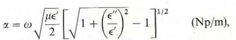
Show that the attenuation and phase constants for a transmission line with perfect conductors separated by a lossy dielectric that has a complex permittivity = - j " are, respectively
Question
A d-c generator of voltage V g and internal resistance R g is connected to a lossy transmission line characterized by a resistance per unit length R and a conductance per unit length G.
a) Write the governing voltage and current transmission-line equations.
b) Find the general solutions for V(z) and I (z).
c) Specialize the solutions in part (b) to those for an infinite line.
d) Specialize the solutions in part (b) to those for a finite line of length
 that is terminated in a load resistance R L.
a) Write the governing voltage and current transmission-line equations.
b) Find the general solutions for V(z) and I (z).
c) Specialize the solutions in part (b) to those for an infinite line.
d) Specialize the solutions in part (b) to those for a finite line of length
that is terminated in a load resistance R L. Question
Question
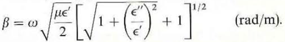
A sinusoidal voltage generator with
 and internal impedance Z g = R 0 is connected to a lossless transmission line having a characteristic impedance R 0 = 50 ( ). The line is
 meters long and is terminated in a load resistance R L = 25 ( ). Find
(a) V h I i V L , and I L ;
(b) the standing-wave ratio on the line; and
(c) the average power delivered to the load. Compare the result in part (c) with the case where R L = 50 ( ).
and internal impedance Z g = R 0 is connected to a lossless transmission line having a characteristic impedance R 0 = 50 ( ). The line is meters long and is terminated in a load resistance R L = 25 ( ). Find(a) V h I i V L , and I L ;
(b) the standing-wave ratio on the line; and
(c) the average power delivered to the load. Compare the result in part (c) with the case where R L = 50 ( ).
Question
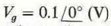
A lossless, air-dielectric, open-circuited transmission line of characteristic resistance R 0 and length
 is initially charged to a voltage V 0 At t = 0 the line is connected to a resistance R, as shown in Fig. 9- 46. Determine V R (t) and I R (t) for
0 t 5
 /c:
/c:
a) if R = 2R 0 ,
b) if R = R 0 / 2.
FIGURE : An initially charged line connected to a resistance (Problem 9- 38).
is initially charged to a voltage V 0 At t = 0 the line is connected to a resistance R, as shown in Fig. 9- 46. Determine V R (t) and I R (t) for0 t 5
/c: a) if R = 2R 0 ,
b) if R = R 0 / 2.
FIGURE : An initially charged line connected to a resistance (Problem 9- 38).
Question
Question
Question
Question
Question
Question
Question
Question
Question
Question
Question
Question
Question
Question
Refer to Fig. 9- 26(a) but change the load from a pure inductance to a series combination of R L = 10 ( ) and L L = 48 (µH). Assume that V 0 = 100 (V), R 0 = 50 ( ),
 = 900 (m), and u = c.
a) Find the expressions for the current in and the voltage across the load as functions of t.
b) Sketch the current and voltage distributions along the transmission line at t 1 = 4 (µS).
= 900 (m), and u = c.a) Find the expressions for the current in and the voltage across the load as functions of t.
b) Sketch the current and voltage distributions along the transmission line at t 1 = 4 (µS).
Question
Question
Question
Question
Question
Question
Question
Question
Question
Question
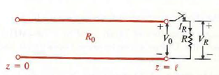
The input impedance of an open- or short-circuited lossy transmission line has both a resistive and a reactive component. Prove that the input impedance of a very short section
![The input impedance of an open- or short-circuited lossy transmission line has both a resistive and a reactive component. Prove that the input impedance of a very short section of a slightly lossy line ( 1 and 1) is approximately (a) a) Z in = (R + j L ) with a short-circuit termination. b) Z in = ( G - j C)/[ G 2 + ( C) 2 ] with an open-circuit termination.<div style=padding-top: 35px>](https://storage.examlex.com/SM4967/11eb823e_d791_50c9_b220_192acb24cdca_SM4967_11.jpg) of a slightly lossy line (
of a slightly lossy line (
![The input impedance of an open- or short-circuited lossy transmission line has both a resistive and a reactive component. Prove that the input impedance of a very short section of a slightly lossy line ( 1 and 1) is approximately (a) a) Z in = (R + j L ) with a short-circuit termination. b) Z in = ( G - j C)/[ G 2 + ( C) 2 ] with an open-circuit termination.<div style=padding-top: 35px>](https://storage.examlex.com/SM4967/11eb823e_d791_50ca_b220_f98a91b8ca36_SM4967_11.jpg) 1 and
1 and
![The input impedance of an open- or short-circuited lossy transmission line has both a resistive and a reactive component. Prove that the input impedance of a very short section of a slightly lossy line ( 1 and 1) is approximately (a) a) Z in = (R + j L ) with a short-circuit termination. b) Z in = ( G - j C)/[ G 2 + ( C) 2 ] with an open-circuit termination.<div style=padding-top: 35px>](https://storage.examlex.com/SM4967/11eb823e_d791_50cb_b220_a3496b0c879b_SM4967_11.jpg) 1) is approximately
1) is approximately
(a) a) Z in = (R + j L )
![The input impedance of an open- or short-circuited lossy transmission line has both a resistive and a reactive component. Prove that the input impedance of a very short section of a slightly lossy line ( 1 and 1) is approximately (a) a) Z in = (R + j L ) with a short-circuit termination. b) Z in = ( G - j C)/[ G 2 + ( C) 2 ] with an open-circuit termination.<div style=padding-top: 35px>](https://storage.examlex.com/SM4967/11eb823e_d791_50cc_b220_8d036c9d1eaf_SM4967_11.jpg) with a short-circuit termination.
with a short-circuit termination.
b) Z in = ( G - j C)/[ G 2 + ( C) 2 ]
![The input impedance of an open- or short-circuited lossy transmission line has both a resistive and a reactive component. Prove that the input impedance of a very short section of a slightly lossy line ( 1 and 1) is approximately (a) a) Z in = (R + j L ) with a short-circuit termination. b) Z in = ( G - j C)/[ G 2 + ( C) 2 ] with an open-circuit termination.<div style=padding-top: 35px>](https://storage.examlex.com/SM4967/11eb823e_d791_50cd_b220_6346ac22a6fa_SM4967_11.jpg) with an open-circuit termination.
with an open-circuit termination.
of a slightly lossy line ( 1 and 1) is approximately(a) a) Z in = (R + j L )
with a short-circuit termination. b) Z in = ( G - j C)/[ G 2 + ( C) 2 ]
with an open-circuit termination. Question
Question
Question
Refer to Fig. 9- 28(a) but change the load from a pure capacitance to a parallel combination of C L = 14 (nF) and R L = 1000 ( ). Assume that V 0 = 100 (V), R 0 = 50 ( ),
 = 900 (m), and u = c.
a) Find the expressions for the current in and the voltage across the load as functions of t.
b) Sketch the current and voltage distributions along the transmission line at t I = 4 (,µs).
= 900 (m), and u = c. a) Find the expressions for the current in and the voltage across the load as functions of t.
b) Sketch the current and voltage distributions along the transmission line at t I = 4 (,µs).
Question
Question
Question
Question
Question
Question
Question
Question
Neglecting fringe fields, prove analytically that a y-polarized TEM wave that propagates along a parallel-plate transmission line in + z-direction has the following properties:
 and
and
 .
.
and . Question
The following characteristics have been measured on a lossy transmission line at 100 (MHz):
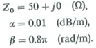
Determine R , L , G , and C for the line.
Determine R , L , G , and C for the line.
Question
Question
Question
A d-e voltage V 0 is applied at t = 0 directly to the input terminals of an open-circuited lossless transmission line of length
 as in Fig. 9- 45. Sketch the voltage and current waves on the line (in the manner of Fig. 9- 16) for the following
time intervals:
a) 0 t T(=
 /u)
/u)
b) T t 2T
c) 2T t 3T
d) 3T t 4T
What happens after t = 4T
Figure: A dc voltage applied to an open-circuited line.).
as in Fig. 9- 45. Sketch the voltage and current waves on the line (in the manner of Fig. 9- 16) for the followingtime intervals:
a) 0 t T(=
/u) b) T t 2T
c) 2T t 3T
d) 3T t 4T
What happens after t = 4T
Figure: A dc voltage applied to an open-circuited line.).
Question
Question
Question
Question
Question
Question
On a line of length
 , what is the relation between the line's characteristic impedance and propagation constant and its open- and short-circuit input impedances
, what is the relation between the line's characteristic impedance and propagation constant and its open- and short-circuit input impedances Question
Question
Question
Question
Question
Question
Question
Question
Question
Question
Question
Question
Question
Question
Question
Question
Question
Question
Question
Prove that a maximum power is transferred from a voltage source with an internal impedance Z g to a load impedance Z L over a lossless transmission line when
 , where Z i is the impedance looking into the loaded line. What is the maximum power-transfer efficiency
, where Z i is the impedance looking into the loaded line. What is the maximum power-transfer efficiency Question
Question
Question
A d-e voltage V 0 is applied at t = 0 to the input terminals of an open circuited air-dielectric line of a length t thro ugh a series resistance equa l to R 0 /2, where R 0 is the characteristic resistance of the line.
a) Draw the voltage and current reflection diagrams.
b) Sketch V(O,
 ) and and I (0,
 ).
).
c) Sketch V(
 /2, t) and I (
 2, t).
a) Draw the voltage and current reflection diagrams.
b) Sketch V(O,
) and and I (0, ). c) Sketch V(
/2, t) and I ( 2, t). Question

Unlock Deck
Sign up to unlock the cards in this deck!
Unlock Deck
Unlock Deck
1/109
Play
Full screen (f)
Deck 9: Theory and Application of Transmission Lines
1
What are striplines
Strip lines are modified forms of parallel-plate transmission lines. Making of parallel plate transmission lines using solid state microwave devices and systems is called strip lines.
2
Write the general transmission-line equations for arbitrary time dependence and for time-harmonic time dependence.
Arbitrary time dependence transmission line equations are the set of first order partial differential equations.
Consider the transmission line equations for arbitrary time dependence.
 Where,
R is the resistance per unit length,
L is the inductance per unit length,
G is the conductance per unit length,
C is the capacitance per unit length,
 denotes instantaneous voltages at z ,
 denotes instantaneous currents at z.
Consider the transmission line equations for the time-harmonic time dependence.
 Where,
 ,
,
 are functions of the space coordinate z.
Thus, the transmission line equations for arbitrary time dependence are
 and the transmission line equation for time harmonic time dependence are
 .
.
Consider the transmission line equations for arbitrary time dependence.
Where,R is the resistance per unit length,
L is the inductance per unit length,
G is the conductance per unit length,
C is the capacitance per unit length,
denotes instantaneous voltages at z , denotes instantaneous currents at z.Consider the transmission line equations for the time-harmonic time dependence.
Where, , are functions of the space coordinate z.Thus, the transmission line equations for arbitrary time dependence are
and the transmission line equation for time harmonic time dependence are . 3
On what factors does the input impedance of a transmission line depend
Consider the equation for input impedance of the line.
 Here,
Here,
 is the input impedance
 is the characteristic impedance
 is the load impedance
 is the length of the transmission line
The input impedance of a transmission line depends on the characteristic and load impedances of the line.
There are various other factors affecting the input impedance.
(1) When the line is open-circuited, its input impedance is purely reactive
(2) For a short open-circuited transmission line, the input impedance is purely capacitive
(3) For a short short-circuited transmission line, the input impedance is purely inductive
Thus, the input impedance of a transmission line depends on the size of the transmission line, and also whether it is short circuited or open circuited.
Here, is the input impedance is the characteristic impedance is the load impedance is the length of the transmission lineThe input impedance of a transmission line depends on the characteristic and load impedances of the line.
There are various other factors affecting the input impedance.
(1) When the line is open-circuited, its input impedance is purely reactive
(2) For a short open-circuited transmission line, the input impedance is purely capacitive
(3) For a short short-circuited transmission line, the input impedance is purely inductive
Thus, the input impedance of a transmission line depends on the size of the transmission line, and also whether it is short circuited or open circuited.
4
Define the bandwidth and the quality factor, Q, of a parallel resonant circuit.
Unlock Deck
Unlock for access to all 109 flashcards in this deck.
Unlock Deck
k this deck
5
A battery of voltage V 0 is applied through a series resistance R g to the input terminals of a lossless transmission line having a characteristic resistance R 0 and a load resistance R L at the far end. What is the amplitude of the first transient voltage wave traveling from the battery to the load What is the amplitude of the first reflected voltage wave from the load to the battery
Unlock Deck
Unlock for access to all 109 flashcards in this deck.
Unlock Deck
k this deck
6
For a given load impedance Z L on a lossless line of characteristic impedance Z 0 , how do we use a Smith chart to determine (a) the reflection coefficient, and (b) the standing-wave ratio
Unlock Deck
Unlock for access to all 109 flashcards in this deck.
Unlock Deck
k this deck
7
Explain the single-stub method for impedance matching on a transmission line.
Unlock Deck
Unlock for access to all 109 flashcards in this deck.
Unlock Deck
k this deck
8
Show that the attenuation and phase constants for a transmission line with perfect conductors separated by a lossy dielectric that has a complex permittivity = - j " are, respectively
Unlock Deck
Unlock for access to all 109 flashcards in this deck.
Unlock Deck
k this deck
9
A d-c generator of voltage V g and internal resistance R g is connected to a lossy transmission line characterized by a resistance per unit length R and a conductance per unit length G.
a) Write the governing voltage and current transmission-line equations.
b) Find the general solutions for V(z) and I (z).
c) Specialize the solutions in part (b) to those for an infinite line.
d) Specialize the solutions in part (b) to those for a finite line of length
that is terminated in a load resistance R L.
a) Write the governing voltage and current transmission-line equations.
b) Find the general solutions for V(z) and I (z).
c) Specialize the solutions in part (b) to those for an infinite line.
d) Specialize the solutions in part (b) to those for a finite line of length
that is terminated in a load resistance R L. Unlock Deck
Unlock for access to all 109 flashcards in this deck.
Unlock Deck
k this deck
10
A lossless quarter-wave line section of characteristic impedance R 0 is terminated with an inductive load impedance Z L = R L +jX L.
Prove that the input impedance is effectively a resistance R i in parallel with a capacitive reactance X i Determine Ri , and X i in terms of R 0 , R L , and X L.
Find the ratio of the magnitude of the voltage at the input to that at the load (voltage transformation ratio, |V in |/|V L |) in terms of R 0 and Z L
Unlock Deck
Unlock for access to all 109 flashcards in this deck.
Unlock Deck
k this deck
11
A sinusoidal voltage generator with
and internal impedance Z g = R 0 is connected to a lossless transmission line having a characteristic impedance R 0 = 50 ( ). The line is
meters long and is terminated in a load resistance R L = 25 ( ). Find
(a) V h I i V L , and I L ;
(b) the standing-wave ratio on the line; and
(c) the average power delivered to the load. Compare the result in part (c) with the case where R L = 50 ( ).
and internal impedance Z g = R 0 is connected to a lossless transmission line having a characteristic impedance R 0 = 50 ( ). The line is meters long and is terminated in a load resistance R L = 25 ( ). Find(a) V h I i V L , and I L ;
(b) the standing-wave ratio on the line; and
(c) the average power delivered to the load. Compare the result in part (c) with the case where R L = 50 ( ).
Unlock Deck
Unlock for access to all 109 flashcards in this deck.
Unlock Deck
k this deck
12
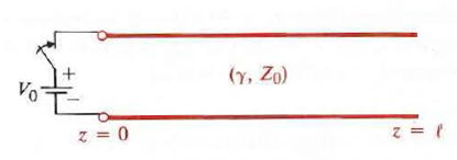
A lossless, air-dielectric, open-circuited transmission line of characteristic resistance R 0 and length
is initially charged to a voltage V 0 At t = 0 the line is connected to a resistance R, as shown in Fig. 9- 46. Determine V R (t) and I R (t) for
0 t 5
/c:
a) if R = 2R 0 ,
b) if R = R 0 / 2.
FIGURE : An initially charged line connected to a resistance (Problem 9- 38).
is initially charged to a voltage V 0 At t = 0 the line is connected to a resistance R, as shown in Fig. 9- 46. Determine V R (t) and I R (t) for0 t 5
/c: a) if R = 2R 0 ,
b) if R = R 0 / 2.
FIGURE : An initially charged line connected to a resistance (Problem 9- 38).
Unlock Deck
Unlock for access to all 109 flashcards in this deck.
Unlock Deck
k this deck
13
The input impedance of a short-circuited lossy transmission line of length 1.5 (m) ( /2) and characteristic impedance 100 ( ) (approximately real) is 40 - j280 ( ).
a) Find a and of the line.
b) Determine the input impedance if the short-circuit is replaced by a load impedance Z L = 50 + J 50 ( ).
c) Find the input impedance of the short-circuited line for a line length 0.15 .
a) Find a and of the line.
b) Determine the input impedance if the short-circuit is replaced by a load impedance Z L = 50 + J 50 ( ).
c) Find the input impedance of the short-circuited line for a line length 0.15 .
Unlock Deck
Unlock for access to all 109 flashcards in this deck.
Unlock Deck
k this deck
14
Explain the double-stub method for impedance matching on a transmission line.
Unlock Deck
Unlock for access to all 109 flashcards in this deck.
Unlock Deck
k this deck
15
Describe how the characteristic impedance of a parallel-plate transmission line depends on plate width and dielectric thickness.
Unlock Deck
Unlock for access to all 109 flashcards in this deck.
Unlock Deck
k this deck
16
Define propagation constant and characteristic impedance of a transmission line. Write their general expressions in terms of R , L , G , and C for sinusoidal excitation.
Unlock Deck
Unlock for access to all 109 flashcards in this deck.
Unlock Deck
k this deck
17
What is the input impedance of an open-circuited lossless transmission line if the length of the line is (a) /4, (b) /2, and (c) 3 /4
Unlock Deck
Unlock for access to all 109 flashcards in this deck.
Unlock Deck
k this deck
18
Define voltage reflection coefficient. Is it the same as "current reflection coefficient" Explain.
Unlock Deck
Unlock for access to all 109 flashcards in this deck.
Unlock Deck
k this deck
19
In Question, what are the amplitudes of the first current wave traveling from the battery to the load and the first reflected current wave from the load to the battery
Problem:
A battery of voltage V 0 is applied through a series resistance R g to the input terminals of a lossless transmission line having a characteristic resistance R 0 and a load resistance R L at the far end. What is the amplitude of the first transient voltage wave traveling from the battery to the load What is the amplitude of the first reflected voltage wave from the load to the battery
Unlock Deck
Unlock for access to all 109 flashcards in this deck.
Unlock Deck
k this deck
20
Why does a change of half a wavelength in line length correspond to a complete revolution on a Smith chart
Unlock Deck
Unlock for access to all 109 flashcards in this deck.
Unlock Deck
k this deck
21
Compare the relative advantages and disadvantages of the single-stub and the double-stub methods of impedance matching.
Unlock Deck
Unlock for access to all 109 flashcards in this deck.
Unlock Deck
k this deck
22
In the derivation of the approximate formulas of and Z 0 for low-loss lines in Subsection 9- 3.1, all terms containing the second and higher powers o f (R/ L ) and (G/ C ) were neglected in comparison with unity. At lower frequencies, better approximations than those given in Eqs. (9- 54) and (9- 58) may be required. Find new formulas for and Z 0 for low-loss lines that retain terms containing ( R/ L ) 2 and ( G/ C ) 2 Obtain the corresponding expression for phase velocity.
Unlock Deck
Unlock for access to all 109 flashcards in this deck.
Unlock Deck
k this deck
23
A generator with an open-circuit voltage v g ( t )= 10 sin 8000 t (V) and internal impedance Z g = 40 + j 30 ( ) is connected to a 50-( ) distortionless line. The line has a resistance of 0.5 ( /m), and its lossy dielectric medium has a loss tangent of 0.18%. The line is 50 (m) long and is terminated in a matched load. Find (a) the instantaneous expressions for the voltage and current at an arbitrary location on the line, (b) the instantaneous expressions for the voltage and current at the load, and (c) the average power transmitted to the load.
Unlock Deck
Unlock for access to all 109 flashcards in this deck.
Unlock Deck
k this deck
24
75 ( ) lossless line is terminated in a load impedance Z L = R L + jX L.
What must be the relation between R L and X L in order that the standing-wave ratio on the line be 3
Find Z L , if R L = 150 ( ).
Where does the voltage minimum nearest to the load occur on the line for part (b)
What must be the relation between R L and X L in order that the standing-wave ratio on the line be 3
Find Z L , if R L = 150 ( ).
Where does the voltage minimum nearest to the load occur on the line for part (b)
Unlock Deck
Unlock for access to all 109 flashcards in this deck.
Unlock Deck
k this deck
25
Consider a lossless transmission line of a characteristic impedance R 0 A time-harmonic voltage source of an amplitude V g and an internal impedance R g = R 0 is connected to the input terminals of the line, which is terminated with a load impedance Z L = R L + jX L Let P inc be the average incident power associated with the wave travelling in the +z-directio n.
a) Find the expression for P inc in terms of V g and R 0
b) Find the expression for the average power P L delivered to the load in terms of V g and the reflection coefficient
c) Express the ratio P L / P inc in terms of the standing-wave ratio S.
d) For V g = 100 (V), R g = R o =50 ( ), Z L =50- j25 (0) determine P inc , , S , P L.
Unlock Deck
Unlock for access to all 109 flashcards in this deck.
Unlock Deck
k this deck
26
Refer to Fig. 9- 26(a) but change the load from a pure inductance to a series combination of R L = 10 ( ) and L L = 48 (µH). Assume that V 0 = 100 (V), R 0 = 50 ( ),
= 900 (m), and u = c.
a) Find the expressions for the current in and the voltage across the load as functions of t.
b) Sketch the current and voltage distributions along the transmission line at t 1 = 4 (µS).
= 900 (m), and u = c.a) Find the expressions for the current in and the voltage across the load as functions of t.
b) Sketch the current and voltage distributions along the transmission line at t 1 = 4 (µS).
Unlock Deck
Unlock for access to all 109 flashcards in this deck.
Unlock Deck
k this deck
27
A dipole antenna having an input impedance of 73 ( ) is fed by a 200-(MHz) source through a 300-( ) two-wire transmission line. Design a quarter-wave two-wire air line with a 2-(cm) spacing to match the antenna to the 300-( ) line.
Unlock Deck
Unlock for access to all 109 flashcards in this deck.
Unlock Deck
k this deck
28
Why are the stubs used in impedance matching usually of the short-circuited type instead of the open-circuited type
Unlock Deck
Unlock for access to all 109 flashcards in this deck.
Unlock Deck
k this deck
29
Compare the velocity of TEM-wave propagation along a parallel-plate transmission line with that in an unbounded medium.
Unlock Deck
Unlock for access to all 109 flashcards in this deck.
Unlock Deck
k this deck
30
What is the phase relationship between the voltage and current waves on an infinitely long transmission line
Unlock Deck
Unlock for access to all 109 flashcards in this deck.
Unlock Deck
k this deck
31
What is the input impedance of a short-circuited lossless transmission line if the length of the line is (a) /4, (b) /2, and (c) 3 /4
Unlock Deck
Unlock for access to all 109 flashcards in this deck.
Unlock Deck
k this deck
32
Define standing-wave ratio. How is it related to voltage and current reflection coefficients
Unlock Deck
Unlock for access to all 109 flashcards in this deck.
Unlock Deck
k this deck
33
What are reflection diagrams of transmission lines For what purposes are they useful
Unlock Deck
Unlock for access to all 109 flashcards in this deck.
Unlock Deck
k this deck
34
Given an impedance Z = R + jX , what procedure do we follow to find the admittance Y = 1/ Z on a Smith chart
Unlock Deck
Unlock for access to all 109 flashcards in this deck.
Unlock Deck
k this deck
35
Obtain approximate expressions for and Z 0 for a lossy transmission line at very low frequencies such that L R and C G.
Unlock Deck
Unlock for access to all 109 flashcards in this deck.
Unlock Deck
k this deck
36
The input impedance of an open- or short-circuited lossy transmission line has both a resistive and a reactive component. Prove that the input impedance of a very short section
of a slightly lossy line (
1 and
1) is approximately
(a) a) Z in = (R + j L )
with a short-circuit termination.
b) Z in = ( G - j C)/[ G 2 + ( C) 2 ]
with an open-circuit termination.
of a slightly lossy line ( 1 and 1) is approximately(a) a) Z in = (R + j L )
with a short-circuit termination. b) Z in = ( G - j C)/[ G 2 + ( C) 2 ]
with an open-circuit termination. Unlock Deck
Unlock for access to all 109 flashcards in this deck.
Unlock Deck
k this deck
37
Consider a lossless transmission line.
(a) Determine the line's characteristic resistance so that it will have a minimum possible standing-wave ratio for a load impedance 40 + j30 ( ).
(b) Find this minimum standing-wave ratio and the corresponding voltage reflection coefficient.
(c) Find the location of the voltage minimum nearest to the load.
Unlock Deck
Unlock for access to all 109 flashcards in this deck.
Unlock Deck
k this deck
38
A sinusoidal voltage generator v 9 = 110 sin t (V) and internal impedance Z9 = 50 ( ) is connected to a quarter-wave lossless line having a characteristic impedance R 0 = 50 ( ) that is terminated in a purely reactive load Z L = j50 ( ).
a) Obtain the voltage and current phasor expressions V( z') and I(z').
b) Write the instantaneous voltage and current expressions v(z', t) and i(z', t).
c) Obtain the instantaneous power and the average power delivered to the load.
a) Obtain the voltage and current phasor expressions V( z') and I(z').
b) Write the instantaneous voltage and current expressions v(z', t) and i(z', t).
c) Obtain the instantaneous power and the average power delivered to the load.
Unlock Deck
Unlock for access to all 109 flashcards in this deck.
Unlock Deck
k this deck
39
Refer to Fig. 9- 28(a) but change the load from a pure capacitance to a parallel combination of C L = 14 (nF) and R L = 1000 ( ). Assume that V 0 = 100 (V), R 0 = 50 ( ),
= 900 (m), and u = c.
a) Find the expressions for the current in and the voltage across the load as functions of t.
b) Sketch the current and voltage distributions along the transmission line at t I = 4 (,µs).
= 900 (m), and u = c. a) Find the expressions for the current in and the voltage across the load as functions of t.
b) Sketch the current and voltage distributions along the transmission line at t I = 4 (,µs).
Unlock Deck
Unlock for access to all 109 flashcards in this deck.
Unlock Deck
k this deck
40
The single-stub method is used to match a load impedance 25 + j25 ) to a 50 ( ) transmission line.
a) Find the required length and position of a short-circuited stub made of a section of the same 50 ( ) line.
b) Repeat part (a) assuming that the short-circuited stub is made of a section of a line that has a characteristic impedance of 75 ( ).
a) Find the required length and position of a short-circuited stub made of a section of the same 50 ( ) line.
b) Repeat part (a) assuming that the short-circuited stub is made of a section of a line that has a characteristic impedance of 75 ( ).
Unlock Deck
Unlock for access to all 109 flashcards in this deck.
Unlock Deck
k this deck
41
Define suface impedance. How is surface impedance related to the power dissipated in a plate conductor
Unlock Deck
Unlock for access to all 109 flashcards in this deck.
Unlock Deck
k this deck
42
What is meant by a "distortionless line" What relation must the distributed parameters of a line satisfy in order for the line to be distortionless
Unlock Deck
Unlock for access to all 109 flashcards in this deck.
Unlock Deck
k this deck
43
Is the input reactance of a transmission line /8 long inductive or capacitive if it is (a) open-circuited, and (b) short-circuited
Unlock Deck
Unlock for access to all 109 flashcards in this deck.
Unlock Deck
k this deck
44
Explain how the value of a terminating resistance can be determined by measuring the standing-wave ratio on a lossless transmission line.
Unlock Deck
Unlock for access to all 109 flashcards in this deck.
Unlock Deck
k this deck
45
How do the voltage and current reflection diagrams of a terminated line differ
Unlock Deck
Unlock for access to all 109 flashcards in this deck.
Unlock Deck
k this deck
46
Given an admittance Y = G + jB , how do we use a Smith chart to find the impedance Z = 1/ Y
Unlock Deck
Unlock for access to all 109 flashcards in this deck.
Unlock Deck
k this deck
47
Neglecting fringe fields, prove analytically that a y-polarized TEM wave that propagates along a parallel-plate transmission line in + z-direction has the following properties:
and
.
and . Unlock Deck
Unlock for access to all 109 flashcards in this deck.
Unlock Deck
k this deck
48
The following characteristics have been measured on a lossy transmission line at 100 (MHz):
Determine R , L , G , and C for the line.
Determine R , L , G , and C for the line.
Unlock Deck
Unlock for access to all 109 flashcards in this deck.
Unlock Deck
k this deck
49
Find the input impedance of a low-loss quarter-wavelength line ( 1):
a) terminated in a short circuit.
b) terminated in an open circuit.
a) terminated in a short circuit.
b) terminated in an open circuit.
Unlock Deck
Unlock for access to all 109 flashcards in this deck.
Unlock Deck
k this deck
50
A lossy transmission line with characteristic impedance Z 0 is terminated in an arbitrary load impedance Z L.
Express the standing-wave ratio S on the line in terms of Z 0 and Z L.
Find in terms of S and Z 0 the impedance looking toward the load at the location of a voltage maximum.
Find the impedance looking toward the load at a location of a voltage minimum.
Express the standing-wave ratio S on the line in terms of Z 0 and Z L.
Find in terms of S and Z 0 the impedance looking toward the load at the location of a voltage maximum.
Find the impedance looking toward the load at a location of a voltage minimum.
Unlock Deck
Unlock for access to all 109 flashcards in this deck.
Unlock Deck
k this deck
51
A d-e voltage V 0 is applied at t = 0 directly to the input terminals of an open-circuited lossless transmission line of length
as in Fig. 9- 45. Sketch the voltage and current waves on the line (in the manner of Fig. 9- 16) for the following
time intervals:
a) 0 t T(=
/u)
b) T t 2T
c) 2T t 3T
d) 3T t 4T
What happens after t = 4T
Figure: A dc voltage applied to an open-circuited line.).
as in Fig. 9- 45. Sketch the voltage and current waves on the line (in the manner of Fig. 9- 16) for the followingtime intervals:
a) 0 t T(=
/u) b) T t 2T
c) 2T t 3T
d) 3T t 4T
What happens after t = 4T
Figure: A dc voltage applied to an open-circuited line.).
Unlock Deck
Unlock for access to all 109 flashcards in this deck.
Unlock Deck
k this deck
52
The Smith chart, constructed on the basis of Eqs. (9-188) and (9- 189) for a Iossless transmission line, is restricted to a unit circle because| | 1. In the case of a lossy line, 2 0 is a complex quantity, and so, in genera l, is the normalized load impedance z L = Z L /Z 0.
a) Show that the phase angle of Z L , L lies between ± 3 /4.
b) Show that | | may be greater than unity.
c) Prove that max. |f| = 2.414.
a) Show that the phase angle of Z L , L lies between ± 3 /4.
b) Show that | | may be greater than unity.
c) Prove that max. |f| = 2.414.
Unlock Deck
Unlock for access to all 109 flashcards in this deck.
Unlock Deck
k this deck
53
A load impedance can be matched to a transmission line also by using a single stub placed in series with the load at an appropriate location, as shown in Fig.. Assuming that Z L = 25 + j 25 ( ), R 0 = 50 ( ), and R 0 = 35 ( ), find d and required for matching.
Unlock Deck
Unlock for access to all 109 flashcards in this deck.
Unlock Deck
k this deck
54
Discuss the similarities and dissimilarities of uniform plane waves in an unbounded media and TEM waves along transmission lines.
Unlock Deck
Unlock for access to all 109 flashcards in this deck.
Unlock Deck
k this deck
55
State the difference between the surface resistance and the resistance per unit length of a parallel-plate transmission line.
Unlock Deck
Unlock for access to all 109 flashcards in this deck.
Unlock Deck
k this deck
56
Is a distortionless line lossless Is a lossy transmission line dispersive Explain.
Unlock Deck
Unlock for access to all 109 flashcards in this deck.
Unlock Deck
k this deck
57
On a line of length
, what is the relation between the line's characteristic impedance and propagation constant and its open- and short-circuit input impedances
, what is the relation between the line's characteristic impedance and propagation constant and its open- and short-circuit input impedances Unlock Deck
Unlock for access to all 109 flashcards in this deck.
Unlock Deck
k this deck
58
Where do the minima of the voltage standing wave on a lossless line with a resistive termination occur (a) if R L R 0 and (b) if R L R 0
Unlock Deck
Unlock for access to all 109 flashcards in this deck.
Unlock Deck
k this deck
59
A d-c voltage is applied to a lossless transmission line. Under what conditions will the transient voltage and current distributions along the line have different shapes Under what conditions will they have the same shape
Unlock Deck
Unlock for access to all 109 flashcards in this deck.
Unlock Deck
k this deck
60
Where is the point representing a short-circuit on a Smith admittance chart
Unlock Deck
Unlock for access to all 109 flashcards in this deck.
Unlock Deck
k this deck
61
The electric and magnetic fields of a general TEM wave traveling in the + z-direction along a transmission line may have both x - and y -components, and both components may be functions of the transverse dimensions.
(a) Find the relations among E x (x, y), E y (x, y), H x (x, y), and H y (x, y).
(b) Verify that all the four field components in part (a) satisfy the two-dimensional Laplace's equation for static fields.
(a) Find the relations among E x (x, y), E y (x, y), H x (x, y), and H y (x, y).
(b) Verify that all the four field components in part (a) satisfy the two-dimensional Laplace's equation for static fields.
Unlock Deck
Unlock for access to all 109 flashcards in this deck.
Unlock Deck
k this deck
62
It is desired to construct uniform transmission lines using polyethylene ( r = 2.25) as the dielectric medium. Assuming negligible losses, (a) find the distance of separation for a 300-( ) two-wire line, where the radius of the conducting wires is 0.6 (mm); and (b) find the inner radius of the outer conductor for a 75-( ) coaxial line, where the radius of the center conductor is 0.6 (mm).
Unlock Deck
Unlock for access to all 109 flashcards in this deck.
Unlock Deck
k this deck
63
A 2-(m) lossless air-spaced transmission line having a characteristic impedance 50 ( ) is terminated with an impedance 40 + j 30 ( ) at an operating frequency of 200 (MHz). Find the input impedance.
Unlock Deck
Unlock for access to all 109 flashcards in this deck.
Unlock Deck
k this deck
64
A transmission line of characteristic impedance R 0 = 50 ( ) is to be matched to a load impedance Z L = 40 +j 10( ) through a length of another transmission line of characteristic impedance R 0. Find the required and R 0 for matching.
Unlock Deck
Unlock for access to all 109 flashcards in this deck.
Unlock Deck
k this deck
65
A 100 (V) d-c voltage is applied at t = 0 to the input terminals of a loss less coaxial cable (R 0 1 = 50 ( ), dielectric constant of insulation E r 1 = 2.25) through an internal resistance R 9 = R 01. The cable is 200 (m) long a nd is connected to a lossJess two-wire line (R 02 = 200 ( ), E, r 2 = 1), which is 400 (m) long and is terminated in its characteristic resistance.
a) Describe the transient behavior of the system and find the. amplitudes of all reflected and transmitted voltage and current waves.
b) Sketch the voltage and current as functions oft at the midpoint of the coaxial cable.
c) Repeat part (b) at the midpoint of the two-wire line.
a) Describe the transient behavior of the system and find the. amplitudes of all reflected and transmitted voltage and current waves.
b) Sketch the voltage and current as functions oft at the midpoint of the coaxial cable.
c) Repeat part (b) at the midpoint of the two-wire line.
Unlock Deck
Unlock for access to all 109 flashcards in this deck.
Unlock Deck
k this deck
66
The characteristic impedance of a given lossless transmission line is 75 ( ). Use a Smith chart to find the input impedance at 200 (MHz) of such a line that is: (a) 1 (m) long and open-circuited, and (b) 0.8 (m) long and short-circuited. Then (c) determine the corresponding input admittances for the lines in parts (a) and (b).
Unlock Deck
Unlock for access to all 109 flashcards in this deck.
Unlock Deck
k this deck
67
The double-stub method is used to match a load impedance 100 + jl 00 ( ) to a lossless transmission line of characteristic impedance 300 ( ). The spacing between the stubs is 3 /8, with one stub connected directly in parallel with the load. Determine the lengths of the stub tuners
(a) if they are both short-circuited, and
(b) if they are both open-circuited.
(a) if they are both short-circuited, and
(b) if they are both open-circuited.
Unlock Deck
Unlock for access to all 109 flashcards in this deck.
Unlock Deck
k this deck
68
What are the three most common types of guiding structures that support TEM waves
Unlock Deck
Unlock for access to all 109 flashcards in this deck.
Unlock Deck
k this deck
69
What is the essential difference between a transmission line and an ordinary electric network
Unlock Deck
Unlock for access to all 109 flashcards in this deck.
Unlock Deck
k this deck
70
Outline a procedure for determining the distributed parameters of a transmission line.
Unlock Deck
Unlock for access to all 109 flashcards in this deck.
Unlock Deck
k this deck
71
What is a "quarter-wave transformer" Why is it not useful for matching a complex load impedance to a low-Joss line
Unlock Deck
Unlock for access to all 109 flashcards in this deck.
Unlock Deck
k this deck
72
Explain how the value of a terminating resistance can be determined by measuring the standing-wave ratio on a lossless transmission line.
Unlock Deck
Unlock for access to all 109 flashcards in this deck.
Unlock Deck
k this deck
73
Why is the concept of reflection coefficients not useful in analyzing the transient behavior of a transmission line terminated in a reactive load
Unlock Deck
Unlock for access to all 109 flashcards in this deck.
Unlock Deck
k this deck
74
Is the standing-wave ratio constant on a transmission line even when the line is lossy Explain.
Unlock Deck
Unlock for access to all 109 flashcards in this deck.
Unlock Deck
k this deck
75
Consider lossless stripline designs for a given characteristic impedance.
a) How should the dielectric thickness, d , be changed for a given plate width, w , if the dielectric constant, r , is doubled
b) How should w be changed for a given d if r is doubled
c) How should w be changed for a given r if d is doubled
d) Will the velocity of propagation remain the same as that for the original line after the changes specified in parts (a), (b), and (c) Explain.
Unlock Deck
Unlock for access to all 109 flashcards in this deck.
Unlock Deck
k this deck
76
Prove that a maximum power is transferred from a voltage source with an internal impedance Z g to a load impedance Z L over a lossless transmission line when
, where Z i is the impedance looking into the loaded line. What is the maximum power-transfer efficiency
, where Z i is the impedance looking into the loaded line. What is the maximum power-transfer efficiency Unlock Deck
Unlock for access to all 109 flashcards in this deck.
Unlock Deck
k this deck
77
The open-circuit and short-circuit impedances measured at the input terminals of an air-spaced transmission line 4 (m) long are 250 / 50 °( ) and 360 /20 ° ( ), respectively.
a) Determine Z 0 , , and of the line.
b) Determine R , L , G , and C.
a) Determine Z 0 , , and of the line.
b) Determine R , L , G , and C.
Unlock Deck
Unlock for access to all 109 flashcards in this deck.
Unlock Deck
k this deck
78
The standing-wave ratio on a lossless 300 ( ) transmission line terminated in an unknown load impedance is 2.0, and the nearest voltage minimum is at a distance 0.32 from the load. Determine
(a) the reflection coefficient of the load,
(b) the unknown load impedance Z L , and
(c) the equivalent length and terminating resistance of a line, such that the input impedance is equal to Z L.
(a) the reflection coefficient of the load,
(b) the unknown load impedance Z L , and
(c) the equivalent length and terminating resistance of a line, such that the input impedance is equal to Z L.
Unlock Deck
Unlock for access to all 109 flashcards in this deck.
Unlock Deck
k this deck
79
A d-e voltage V 0 is applied at t = 0 to the input terminals of an open circuited air-dielectric line of a length t thro ugh a series resistance equa l to R 0 /2, where R 0 is the characteristic resistance of the line.
a) Draw the voltage and current reflection diagrams.
b) Sketch V(O,
) and and I (0,
).
c) Sketch V(
/2, t) and I (
2, t).
a) Draw the voltage and current reflection diagrams.
b) Sketch V(O,
) and and I (0, ). c) Sketch V(
/2, t) and I ( 2, t). Unlock Deck
Unlock for access to all 109 flashcards in this deck.
Unlock Deck
k this deck
80
A load impedance 30 + j 10 ( ) is connected to a lossless transmission line of length 0.101 and characteristic impedance 50 ( ). Use a Smith chart to find (a) the standing-wave ratio, (b) the voltage reflection coefficient, (c) the input impedance, (d) the input admittance, and (e) the location of the voltage minimum on the line.
Unlock Deck
Unlock for access to all 109 flashcards in this deck.
Unlock Deck
k this deck
Unlock Deck
Unlock for access to all 109 flashcards in this deck.


