Deck 6: Internal Effects in Bars, Shafts, Beams and Frames
Full screen (f)
Question
simple beam AB with an overhang BC is loaded as shown in the figure. The bending moment at the midspan of AB is approximately: 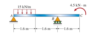
(A) 8 kN ∙ m
(B) 12 kN ∙ m
(C) 17 kN ∙ m
(D) 21 kN ∙ m
(A) 8 kN ∙ m
(B) 12 kN ∙ m
(C) 17 kN ∙ m
(D) 21 kN ∙ m
Question
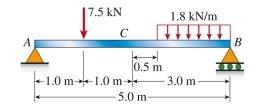
cantilever beam is loaded as shown in the figure. The bending moment at 0.5 m from the support is approximately: 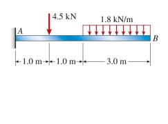
(A) 12.7 kN ∙ m
(B) 14.2 kN ∙ m
(C) 16.1 kN ∙ m
(D) 18.5 kN ∙ m
(A) 12.7 kN ∙ m
(B) 14.2 kN ∙ m
(C) 16.1 kN ∙ m
(D) 18.5 kN ∙ m
Question
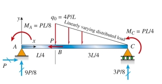
The simply supported beam ABC shown below is acted upon by applied axial force P at B; by linearly varying distributed load q on BC; and by applied moments  . Reaction forces are given in the figure
In terms of load variable P. The axial force (N), shear (V), and bending moment (M) at mid-span are (in terms
Of variables L and P):
 Stresses and strain
. Reaction forces are given in the figureIn terms of load variable P. The axial force (N), shear (V), and bending moment (M) at mid-span are (in terms
Of variables L and P):
Stresses and strain Question
T-shaped simple beam has a cable with force P anchored at B and passing over a pulley at E, as shown in the figure. The bending moment just left of C is 1.25 kN ∙ m. The cable force P is approximately: 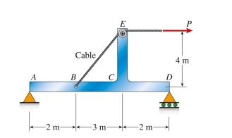
(A) 2.7 kN
(B) 3.9 kN
(C) 4.5 kN
(D) 6.2 kN
(A) 2.7 kN
(B) 3.9 kN
(C) 4.5 kN
(D) 6.2 kN
Question
simply supported beam is loaded as shown in the figure. The bending moment at point C is approximately: 
Question
simple beam (L 5 9 m) with attached bracket BDE has force P 5 5 kN applied downward at E. The bending moment just right of  is approximately:
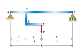
(A) 6 N ∙ m
(B) 10 N ∙ m
(C) 19 N ∙ m
(D) 22 N ∙ m
is approximately: (A) 6 N ∙ m
(B) 10 N ∙ m
(C) 19 N ∙ m
(D) 22 N ∙ m
Question
Reaction forces are given in the figure below for beam ABCDE. The bending moment at C (in kN ∙ m) is: 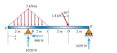
(A) 0.84 kN ∙ m
(B) 0.96 kN ∙ m
(C) 1.04 kN ∙ m
(D) 1.36 kN ∙ m
(A) 0.84 kN ∙ m
(B) 0.96 kN ∙ m
(C) 1.04 kN ∙ m
(D) 1.36 kN ∙ m
Question
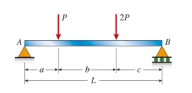
simply supported beam with proportional loading (P 5 4.1 kN) has span length L 5 5 m. Load P is 1.2 m from support A and load 2P is 1.5 m from support B. The bending moment just left of load 2P is approximately: 
Question
L-shaped beam is loaded as shown in the figure. The bending moment at the midpoint of span AB is approximately: 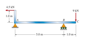
(A) 6.8 kN ∙ m
(B) 10.1 kN ∙ m
(C) 12.3 kN ∙ m
(D) 15.5 kN ∙ m
(A) 6.8 kN ∙ m
(B) 10.1 kN ∙ m
(C) 12.3 kN ∙ m
(D) 15.5 kN ∙ m
Question
cable with known tension force T is anchored at C and passes over a frictionless drum (see figure). The pin force components 
 or the pin connection at B are:
 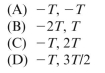 T
T 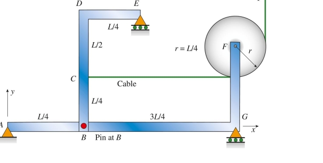
or the pin connection at B are: T 
Unlock Deck
Sign up to unlock the cards in this deck!
Unlock Deck
Unlock Deck
1/10
Play
Full screen (f)
Deck 6: Internal Effects in Bars, Shafts, Beams and Frames
1
simple beam AB with an overhang BC is loaded as shown in the figure. The bending moment at the midspan of AB is approximately:
(A) 8 kN ∙ m
(B) 12 kN ∙ m
(C) 17 kN ∙ m
(D) 21 kN ∙ m
(A) 8 kN ∙ m
(B) 12 kN ∙ m
(C) 17 kN ∙ m
(D) 21 kN ∙ m
B
2
cantilever beam is loaded as shown in the figure. The bending moment at 0.5 m from the support is approximately:
(A) 12.7 kN ∙ m
(B) 14.2 kN ∙ m
(C) 16.1 kN ∙ m
(D) 18.5 kN ∙ m
(A) 12.7 kN ∙ m
(B) 14.2 kN ∙ m
(C) 16.1 kN ∙ m
(D) 18.5 kN ∙ m
D
3
The simply supported beam ABC shown below is acted upon by applied axial force P at B; by linearly varying distributed load q on BC; and by applied moments . Reaction forces are given in the figure
In terms of load variable P. The axial force (N), shear (V), and bending moment (M) at mid-span are (in terms
Of variables L and P): Stresses and strain
. Reaction forces are given in the figureIn terms of load variable P. The axial force (N), shear (V), and bending moment (M) at mid-span are (in terms
Of variables L and P):
Stresses and strainD
4
T-shaped simple beam has a cable with force P anchored at B and passing over a pulley at E, as shown in the figure. The bending moment just left of C is 1.25 kN ∙ m. The cable force P is approximately:
(A) 2.7 kN
(B) 3.9 kN
(C) 4.5 kN
(D) 6.2 kN
(A) 2.7 kN
(B) 3.9 kN
(C) 4.5 kN
(D) 6.2 kN
Unlock Deck
Unlock for access to all 10 flashcards in this deck.
Unlock Deck
k this deck
5
simply supported beam is loaded as shown in the figure. The bending moment at point C is approximately:
Unlock Deck
Unlock for access to all 10 flashcards in this deck.
Unlock Deck
k this deck
6
simple beam (L 5 9 m) with attached bracket BDE has force P 5 5 kN applied downward at E. The bending moment just right of is approximately:
(A) 6 N ∙ m
(B) 10 N ∙ m
(C) 19 N ∙ m
(D) 22 N ∙ m
is approximately: (A) 6 N ∙ m
(B) 10 N ∙ m
(C) 19 N ∙ m
(D) 22 N ∙ m
Unlock Deck
Unlock for access to all 10 flashcards in this deck.
Unlock Deck
k this deck
7
Reaction forces are given in the figure below for beam ABCDE. The bending moment at C (in kN ∙ m) is:
(A) 0.84 kN ∙ m
(B) 0.96 kN ∙ m
(C) 1.04 kN ∙ m
(D) 1.36 kN ∙ m
(A) 0.84 kN ∙ m
(B) 0.96 kN ∙ m
(C) 1.04 kN ∙ m
(D) 1.36 kN ∙ m
Unlock Deck
Unlock for access to all 10 flashcards in this deck.
Unlock Deck
k this deck
8
simply supported beam with proportional loading (P 5 4.1 kN) has span length L 5 5 m. Load P is 1.2 m from support A and load 2P is 1.5 m from support B. The bending moment just left of load 2P is approximately:
Unlock Deck
Unlock for access to all 10 flashcards in this deck.
Unlock Deck
k this deck
9
L-shaped beam is loaded as shown in the figure. The bending moment at the midpoint of span AB is approximately:
(A) 6.8 kN ∙ m
(B) 10.1 kN ∙ m
(C) 12.3 kN ∙ m
(D) 15.5 kN ∙ m
(A) 6.8 kN ∙ m
(B) 10.1 kN ∙ m
(C) 12.3 kN ∙ m
(D) 15.5 kN ∙ m
Unlock Deck
Unlock for access to all 10 flashcards in this deck.
Unlock Deck
k this deck
10
cable with known tension force T is anchored at C and passes over a frictionless drum (see figure). The pin force components or the pin connection at B are: T
or the pin connection at B are: T Unlock Deck
Unlock for access to all 10 flashcards in this deck.
Unlock Deck
k this deck
Unlock Deck
Unlock for access to all 10 flashcards in this deck.


