Deck 10: Stresses in Beams
Full screen (f)
Question
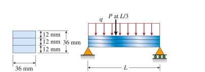
A simply supported laminated beam of length L 5 0.5 m and square cross section weighs 4.8 N. Three strips are glued together to form the beam, with the allowable shear stress in the glued joint equal to 0.3 MPa.
Considering also the weight of the beam, the maximum load P that can be applied at /3 from the left support
Is approximately:
Considering also the weight of the beam, the maximum load P that can be applied at
/3 from the left supportIs approximately:
Question
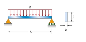
A simply supported steel beam of length L 5 1.5 m and rectangular cross section ( 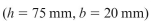 carries a uniform load of
  48 kN/m that includes its own weight. The maximum transverse shear stress on the cross section at 0.25 m from the left support is approximately:
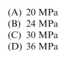
carries a uniform load of 48 kN/m that includes its own weight. The maximum transverse shear stress on the cross section at 0.25 m from the left support is approximately: Question
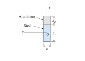
A bimetallic beam of aluminum (  110 GPa) strips has a width of b 5 25 mm; each strip has a thickness of t 5 1.5 mm. A bending moment of 1.75 N ? m is applied about
The z axis. The ratio of the maximum stress in aluminum to that in copper is approximately: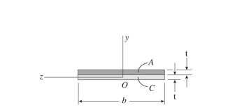
(A) 0.6
(B) 0.8
(C) 1.0
(D) 1.5
110 GPa) strips has a width of b 5 25 mm; each strip has a thickness of t 5 1.5 mm. A bending moment of 1.75 N ? m is applied aboutThe z axis. The ratio of the maximum stress in aluminum to that in copper is approximately:
(A) 0.6
(B) 0.8
(C) 1.0
(D) 1.5
Question
A cantilever wood pole carries force P 5 300 N applied at its free end, as well as its own weight (weight density 5  ). The length of the pole is L 5 0.75 m and the allowable bending stress is 14 MPa. The
  required diameter of the pole is approximately:
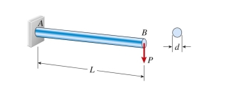
(A) 4.2 cm
(B) 5.5 cm
(C) 6.1 cm
(D) 8.5 cm
). The length of the pole is L 5 0.75 m and the allowable bending stress is 14 MPa. The required diameter of the pole is approximately: (A) 4.2 cm
(B) 5.5 cm
(C) 6.1 cm
(D) 8.5 cm
Question
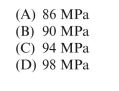
A simply supported wood beam (L 5 5 m) with rectangular cross section (b 5 200 mm, h 5 280 mm) car- ries uniform load q 5 6.5 kN/m includes the weight of the beam. The maximum flexural stress is approximately: 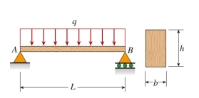
(A) 8.7 MPa
(B) 10.1 MPa
(C) 11.4 MPa
(D) 14.3 MPa
(A) 8.7 MPa
(B) 10.1 MPa
(C) 11.4 MPa
(D) 14.3 MPa
Question
A steel hanger with solid cross section has horizontal force P 5 5.5 kN applied at free end D. Dimension variable b 5 175 mm and allowable normal stress is 150 MPa. Neglect self-weight of the hanger. The required
Diameter of the hanger is approximately: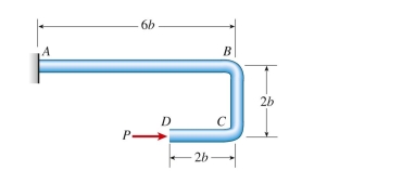
(A) 5 cm
(B) 7 cm
(C) 10 cm
(D) 13 cm
Diameter of the hanger is approximately:
(A) 5 cm
(B) 7 cm
(C) 10 cm
(D) 13 cm
Question
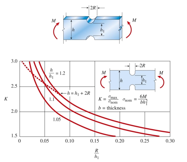
A rectangular beam with semicircular notches has dimen sions  maximum allowable bending stress in the plastic beam is
 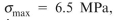 (A) 12 mm (B) 20 mm
(C) 28 mm
(D) 32 mm
maximum allowable bending stress in the plastic beam is (A) 12 mm (B) 20 mm(C) 28 mm
(D) 32 mm
Question
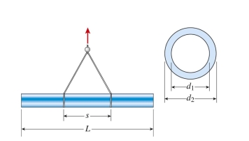
A cast iron pipe (  75 mm) is lifted by a hoist. The lift points are 6 m apart. The maximum bending stress in the pipe is approximately:
75 mm) is lifted by a hoist. The lift points are 6 m apart. The maximum bending stress in the pipe is approximately: Question
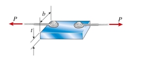
Two thin cables, each having a diameter of d 5 t/6 and carrying tensile loads P, are bolted to the top of a rectangular steel block with cross-sectional dimensions  . The ratio of the maximum tensile to compressive
Stress in the block due to loads P is:
. The ratio of the maximum tensile to compressiveStress in the block due to loads P is:
Question
An aluminum cantilever beam of length L 5 0.65 m carries a distributed load, which includes its own weight, of intensity 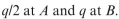 . The beam cross section has a width of 50 mm and a height of 170 mm.
Allowable bending stress is 95 MPa and allowable shear stress The permissible value of load inten-
Sity is approximately:
. The beam cross section has a width of 50 mm and a height of 170 mm.Allowable bending stress is 95 MPa and allowable shear stress
The permissible value of load inten-Sity
is approximately: Question


(A) 0.5
(B) 0.7
(C) 1.2
(D) 1.5
Question

 68 mm, respectively. A bending moment is applied about the z axis resulting in a maximum stress in the aluminum of 55 MPa. The maximum stress in the steel is approximately:
 Plane stress and strain; principal stresses
 Question
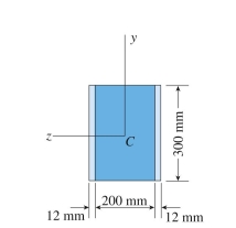
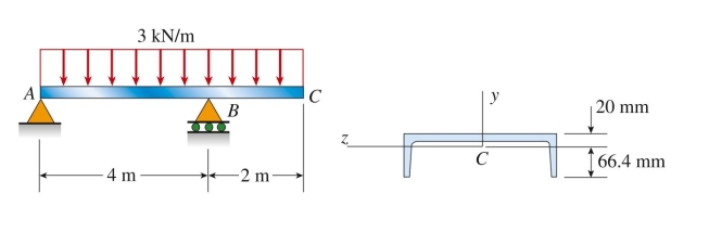
A beam with an overhang is loaded by a uniform load of 3 kN/m over its entire length. Moment of iner- tia  and distances to top and bottom of the beam cross section are 20 mm and 66.4 mm,
Respectively. It is known that reactions at A and B are 4.5 kN and 13.5 kN, respectively. The maximum bending
Stress in the beam is approximately:
and distances to top and bottom of the beam cross section are 20 mm and 66.4 mm,Respectively. It is known that reactions at A and B are 4.5 kN and 13.5 kN, respectively. The maximum bending
Stress in the beam is approximately:
Question
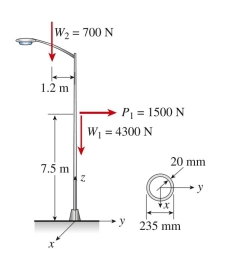
An aluminum light pole weighs 4300 N and supports an arm of weight 700 N, with the arm center of gravity at 1.2 m left of the centroidal axis of the pole. A wind force of 1500 N acts to the right at 7.5 m above
The base. The pole cross section at the base has an outside diameter of 235 mm and thickness of 20 mm. The
Maximum compressive stress at the base is approximately:
The base. The pole cross section at the base has an outside diameter of 235 mm and thickness of 20 mm. The
Maximum compressive stress at the base is approximately:
Question
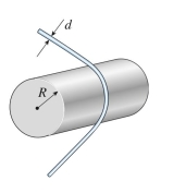
A copper wire (d 5 1.5 mm) is bent around a tube of radius R 5 0.6 m. The maximum normal strain in the wire is approximately: 

Unlock Deck
Sign up to unlock the cards in this deck!
Unlock Deck
Unlock Deck
1/15
Play
Full screen (f)
Deck 10: Stresses in Beams
1
A simply supported laminated beam of length L 5 0.5 m and square cross section weighs 4.8 N. Three strips are glued together to form the beam, with the allowable shear stress in the glued joint equal to 0.3 MPa.
Considering also the weight of the beam, the maximum load P that can be applied at /3 from the left support
Is approximately:
Considering also the weight of the beam, the maximum load P that can be applied at
/3 from the left supportIs approximately:
C
2
A simply supported steel beam of length L 5 1.5 m and rectangular cross section ( carries a uniform load of 48 kN/m that includes its own weight. The maximum transverse shear stress on the cross section at 0.25 m from the left support is approximately:
carries a uniform load of 48 kN/m that includes its own weight. The maximum transverse shear stress on the cross section at 0.25 m from the left support is approximately: B
3
A bimetallic beam of aluminum ( 110 GPa) strips has a width of b 5 25 mm; each strip has a thickness of t 5 1.5 mm. A bending moment of 1.75 N ? m is applied about
The z axis. The ratio of the maximum stress in aluminum to that in copper is approximately:
(A) 0.6
(B) 0.8
(C) 1.0
(D) 1.5
110 GPa) strips has a width of b 5 25 mm; each strip has a thickness of t 5 1.5 mm. A bending moment of 1.75 N ? m is applied aboutThe z axis. The ratio of the maximum stress in aluminum to that in copper is approximately:
(A) 0.6
(B) 0.8
(C) 1.0
(D) 1.5
B
4
A cantilever wood pole carries force P 5 300 N applied at its free end, as well as its own weight (weight density 5 ). The length of the pole is L 5 0.75 m and the allowable bending stress is 14 MPa. The required diameter of the pole is approximately:
(A) 4.2 cm
(B) 5.5 cm
(C) 6.1 cm
(D) 8.5 cm
). The length of the pole is L 5 0.75 m and the allowable bending stress is 14 MPa. The required diameter of the pole is approximately: (A) 4.2 cm
(B) 5.5 cm
(C) 6.1 cm
(D) 8.5 cm
Unlock Deck
Unlock for access to all 15 flashcards in this deck.
Unlock Deck
k this deck
5
A simply supported wood beam (L 5 5 m) with rectangular cross section (b 5 200 mm, h 5 280 mm) car- ries uniform load q 5 6.5 kN/m includes the weight of the beam. The maximum flexural stress is approximately:
(A) 8.7 MPa
(B) 10.1 MPa
(C) 11.4 MPa
(D) 14.3 MPa
(A) 8.7 MPa
(B) 10.1 MPa
(C) 11.4 MPa
(D) 14.3 MPa
Unlock Deck
Unlock for access to all 15 flashcards in this deck.
Unlock Deck
k this deck
6
A steel hanger with solid cross section has horizontal force P 5 5.5 kN applied at free end D. Dimension variable b 5 175 mm and allowable normal stress is 150 MPa. Neglect self-weight of the hanger. The required
Diameter of the hanger is approximately:
(A) 5 cm
(B) 7 cm
(C) 10 cm
(D) 13 cm
Diameter of the hanger is approximately:
(A) 5 cm
(B) 7 cm
(C) 10 cm
(D) 13 cm
Unlock Deck
Unlock for access to all 15 flashcards in this deck.
Unlock Deck
k this deck
7
A rectangular beam with semicircular notches has dimen sions maximum allowable bending stress in the plastic beam is (A) 12 mm (B) 20 mm
(C) 28 mm
(D) 32 mm
maximum allowable bending stress in the plastic beam is (A) 12 mm (B) 20 mm(C) 28 mm
(D) 32 mm
Unlock Deck
Unlock for access to all 15 flashcards in this deck.
Unlock Deck
k this deck
8
A cast iron pipe ( 75 mm) is lifted by a hoist. The lift points are 6 m apart. The maximum bending stress in the pipe is approximately:
75 mm) is lifted by a hoist. The lift points are 6 m apart. The maximum bending stress in the pipe is approximately: Unlock Deck
Unlock for access to all 15 flashcards in this deck.
Unlock Deck
k this deck
9
Two thin cables, each having a diameter of d 5 t/6 and carrying tensile loads P, are bolted to the top of a rectangular steel block with cross-sectional dimensions . The ratio of the maximum tensile to compressive
Stress in the block due to loads P is:
. The ratio of the maximum tensile to compressiveStress in the block due to loads P is:
Unlock Deck
Unlock for access to all 15 flashcards in this deck.
Unlock Deck
k this deck
10
An aluminum cantilever beam of length L 5 0.65 m carries a distributed load, which includes its own weight, of intensity . The beam cross section has a width of 50 mm and a height of 170 mm.
Allowable bending stress is 95 MPa and allowable shear stress The permissible value of load inten-
Sity is approximately:
. The beam cross section has a width of 50 mm and a height of 170 mm.Allowable bending stress is 95 MPa and allowable shear stress
The permissible value of load inten-Sity
is approximately: Unlock Deck
Unlock for access to all 15 flashcards in this deck.
Unlock Deck
k this deck
11
(A) 0.5
(B) 0.7
(C) 1.2
(D) 1.5
Unlock Deck
Unlock for access to all 15 flashcards in this deck.
Unlock Deck
k this deck
12
68 mm, respectively. A bending moment is applied about the z axis resulting in a maximum stress in the aluminum of 55 MPa. The maximum stress in the steel is approximately: Plane stress and strain; principal stresses Unlock Deck
Unlock for access to all 15 flashcards in this deck.
Unlock Deck
k this deck
13
A beam with an overhang is loaded by a uniform load of 3 kN/m over its entire length. Moment of iner- tia and distances to top and bottom of the beam cross section are 20 mm and 66.4 mm,
Respectively. It is known that reactions at A and B are 4.5 kN and 13.5 kN, respectively. The maximum bending
Stress in the beam is approximately:
and distances to top and bottom of the beam cross section are 20 mm and 66.4 mm,Respectively. It is known that reactions at A and B are 4.5 kN and 13.5 kN, respectively. The maximum bending
Stress in the beam is approximately:
Unlock Deck
Unlock for access to all 15 flashcards in this deck.
Unlock Deck
k this deck
14
An aluminum light pole weighs 4300 N and supports an arm of weight 700 N, with the arm center of gravity at 1.2 m left of the centroidal axis of the pole. A wind force of 1500 N acts to the right at 7.5 m above
The base. The pole cross section at the base has an outside diameter of 235 mm and thickness of 20 mm. The
Maximum compressive stress at the base is approximately:
The base. The pole cross section at the base has an outside diameter of 235 mm and thickness of 20 mm. The
Maximum compressive stress at the base is approximately:
Unlock Deck
Unlock for access to all 15 flashcards in this deck.
Unlock Deck
k this deck
15
A copper wire (d 5 1.5 mm) is bent around a tube of radius R 5 0.6 m. The maximum normal strain in the wire is approximately:
Unlock Deck
Unlock for access to all 15 flashcards in this deck.
Unlock Deck
k this deck
Unlock Deck
Unlock for access to all 15 flashcards in this deck.


