Deck 14: Control Circuits
Full screen (f)
Question

In the accompanying figure, the push-to-test switch is a two-circuit _______________ push-button.
Question
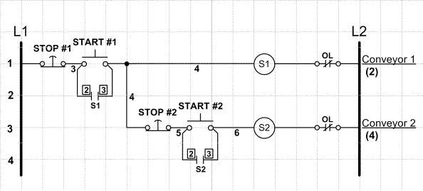
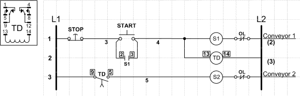
In the accompanying figure, describe the order, if any, in which the motors start running.
Question
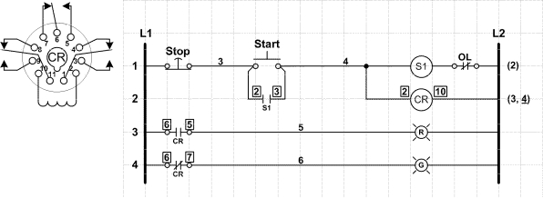
In the accompanying figure, the control circuit uses a relay in place of auxiliary contacts to operate auxiliary contact-controlled status indicator lamps.
Question
In the accompanying figure, the contact connected across the jog pushbutton is a(n) _______________.
Question
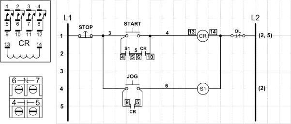
In the accompanying figure, the _______________ circuit uses three momentary contact pushbutton switches.
Question

Describe the circuit in the accompanying figure.
Question
Question
In the accompanying figure, what is the purpose of the control circuit?
Question
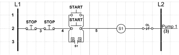
In the accompanying figure, all the stop and start pushbuttons must be wired in parallel.
Question

In the accompanying figure, the jog circuit uses three momentary contact pushbutton switches, and is considered to be safer than other jog circuits that use only momentary contact switches.
Question
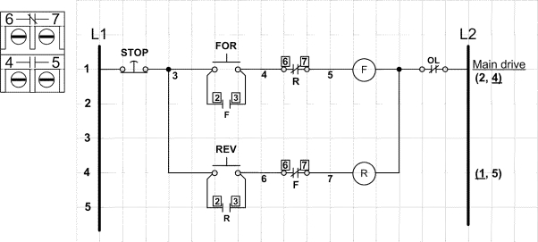
Describe the control circuit in the accompanying figure.
Question
In the accompanying figure, the control circuit diagram uses an eleven-pin, triangle based ice cube relay.
Question
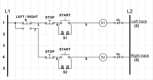
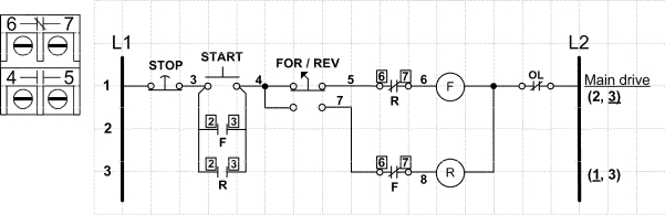
In the accompanying figure, the two-position, two-circuit selector switch allows only one control circuit rung to be _______________ at a time, so simultaneous operation is not possible.
Question
Question
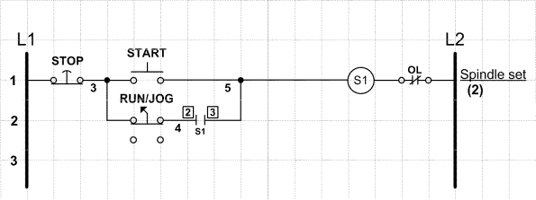
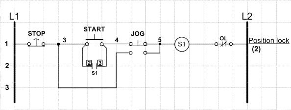
In the accompanying figure, this jog circuit uses two momentary-contact pushbutton switches, and one _______________ switch.
Question

In the accompanying figure, what is the purpose of the jog function?
Question
Describe the control circuit in the accompanying figure.
Question
Describe the control circuit in the accompanying figure.
Question
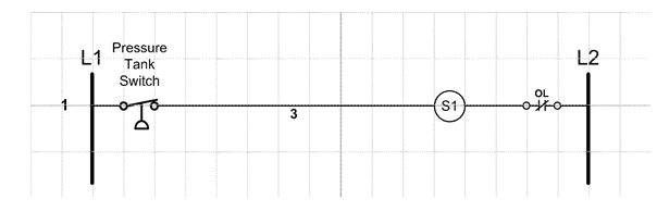
In the accompanying figure, the pressure tank switch pilot device determines when the motor is energized and de-energized by energizing and de-energizing the control coil.
Question
In the accompanying figure, what is the purpose of the control circuit?

Unlock Deck
Sign up to unlock the cards in this deck!
Unlock Deck
Unlock Deck
1/20
Play
Full screen (f)
Deck 14: Control Circuits
1
In the accompanying figure, the push-to-test switch is a two-circuit _______________ push-button.
momentary-contact
2
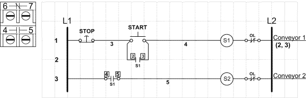
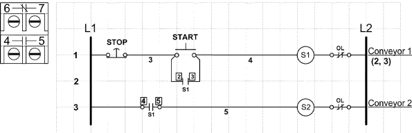
In the accompanying figure, describe the order, if any, in which the motors start running.
The control circuit shows a control circuit where motor 2 cannot start until motor 1 is running.
3
In the accompanying figure, the control circuit uses a relay in place of auxiliary contacts to operate auxiliary contact-controlled status indicator lamps.
True
4
In the accompanying figure, the contact connected across the jog pushbutton is a(n) _______________.
Unlock Deck
Unlock for access to all 20 flashcards in this deck.
Unlock Deck
k this deck
5
In the accompanying figure, the _______________ circuit uses three momentary contact pushbutton switches.
Unlock Deck
Unlock for access to all 20 flashcards in this deck.
Unlock Deck
k this deck
6
Describe the circuit in the accompanying figure.
Unlock Deck
Unlock for access to all 20 flashcards in this deck.
Unlock Deck
k this deck
7
In the accompanying figure, the pin-out information for the buttons is to the left of the diagram.
Unlock Deck
Unlock for access to all 20 flashcards in this deck.
Unlock Deck
k this deck
8
In the accompanying figure, what is the purpose of the control circuit?
Unlock Deck
Unlock for access to all 20 flashcards in this deck.
Unlock Deck
k this deck
9
In the accompanying figure, all the stop and start pushbuttons must be wired in parallel.
Unlock Deck
Unlock for access to all 20 flashcards in this deck.
Unlock Deck
k this deck
10
In the accompanying figure, the jog circuit uses three momentary contact pushbutton switches, and is considered to be safer than other jog circuits that use only momentary contact switches.
Unlock Deck
Unlock for access to all 20 flashcards in this deck.
Unlock Deck
k this deck
11
Describe the control circuit in the accompanying figure.
Unlock Deck
Unlock for access to all 20 flashcards in this deck.
Unlock Deck
k this deck
12
In the accompanying figure, the control circuit diagram uses an eleven-pin, triangle based ice cube relay.
Unlock Deck
Unlock for access to all 20 flashcards in this deck.
Unlock Deck
k this deck
13
In the accompanying figure, the two-position, two-circuit selector switch allows only one control circuit rung to be _______________ at a time, so simultaneous operation is not possible.
Unlock Deck
Unlock for access to all 20 flashcards in this deck.
Unlock Deck
k this deck
14
A reversing motor starter has four contactors and two control coils.
Unlock Deck
Unlock for access to all 20 flashcards in this deck.
Unlock Deck
k this deck
15
In the accompanying figure, this jog circuit uses two momentary-contact pushbutton switches, and one _______________ switch.
Unlock Deck
Unlock for access to all 20 flashcards in this deck.
Unlock Deck
k this deck
16
In the accompanying figure, what is the purpose of the jog function?
Unlock Deck
Unlock for access to all 20 flashcards in this deck.
Unlock Deck
k this deck
17
Describe the control circuit in the accompanying figure.
Unlock Deck
Unlock for access to all 20 flashcards in this deck.
Unlock Deck
k this deck
18
Describe the control circuit in the accompanying figure.
Unlock Deck
Unlock for access to all 20 flashcards in this deck.
Unlock Deck
k this deck
19
In the accompanying figure, the pressure tank switch pilot device determines when the motor is energized and de-energized by energizing and de-energizing the control coil.
Unlock Deck
Unlock for access to all 20 flashcards in this deck.
Unlock Deck
k this deck
20
In the accompanying figure, what is the purpose of the control circuit?
Unlock Deck
Unlock for access to all 20 flashcards in this deck.
Unlock Deck
k this deck
Unlock Deck
Unlock for access to all 20 flashcards in this deck.


