Deck 18: Basic Electric Circuits
Full screen (f)
Question
Question
Question
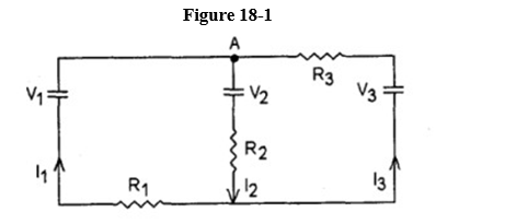
For the circuit illustrated in Figure 18-1, write the Kirchhoff current equation for the node labeled A.
Question
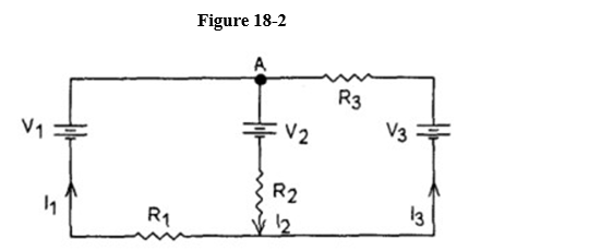
Write the Kirchhoff loop equation for the entire outside loop (see Figure 18-2)
Question
See Figure 18-3. Write the Kirchhoff loop equation for the:
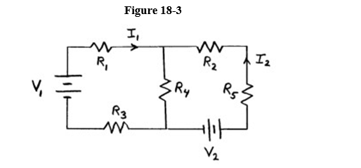
(a) left hand loop in terms of V1, V2, R1, R2, R3, R4, R5, I1 and I2.
(b) right hand loop in terms of V1, V2, R1, R2, R3, R4, R5, I1 and I2.
(a) left hand loop in terms of V1, V2, R1, R2, R3, R4, R5, I1 and I2.
(b) right hand loop in terms of V1, V2, R1, R2, R3, R4, R5, I1 and I2.
Question
Question
Question
Question
Question
Question
Question
Question
Question
Question
Question
Question
A 3.  resistor is connected in parallel with a 6. 11eea409_b6c6_d93c_97f4_a5754f0dddc8_TB9720_11 resistor. This pair is then connected in series with a 4. 11eea409_b6c6_d93c_97f4_a5754f0dddc8_TB9720_11 resistor. These resistors are connected to a battery. What will happen if the 3. 11eea409_b6c6_d93c_97f4_a5754f0dddc8_TB9720_11 resistor burns out, i.e., becomes an infinite resistance?
A) The power dissipated in the circuit will increase.
B) The current in the 6. 11eea409_b6c6_d93c_97f4_a5754f0dddc8_TB9720_11 resistor will increase.
C) The current provided by the battery will not change.
D) The current in the 4. 11eea409_b6c6_d93c_97f4_a5754f0dddc8_TB9720_11 resistor will drop to zero.
resistor is connected in parallel with a 6. 11eea409_b6c6_d93c_97f4_a5754f0dddc8_TB9720_11 resistor. This pair is then connected in series with a 4. 11eea409_b6c6_d93c_97f4_a5754f0dddc8_TB9720_11 resistor. These resistors are connected to a battery. What will happen if the 3. 11eea409_b6c6_d93c_97f4_a5754f0dddc8_TB9720_11 resistor burns out, i.e., becomes an infinite resistance?A) The power dissipated in the circuit will increase.
B) The current in the 6. 11eea409_b6c6_d93c_97f4_a5754f0dddc8_TB9720_11 resistor will increase.
C) The current provided by the battery will not change.
D) The current in the 4. 11eea409_b6c6_d93c_97f4_a5754f0dddc8_TB9720_11 resistor will drop to zero.
Question
Question
Question
Question
In Figure 18-4, which of the following equations is true?
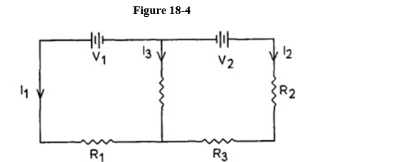
A) V1 - I1 R1 - I2 R2 + V2 - I2 R3 = 0
B) V1 + I1 R1 - I2 R2 - V2 - I3 R4 = 0
C) V1 - I1 R1 + I2 R2 - V2 + I2 R3 = 0
D) V1 I1 R1 + I2 R2 + V2 + I2 R3 = 0
A) V1 - I1 R1 - I2 R2 + V2 - I2 R3 = 0
B) V1 + I1 R1 - I2 R2 - V2 - I3 R4 = 0
C) V1 - I1 R1 + I2 R2 - V2 + I2 R3 = 0
D) V1 I1 R1 + I2 R2 + V2 + I2 R3 = 0
Question
In Figure 18-5, which of the following relations is true?
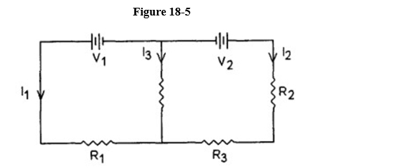
A) I1 + I2 - I3 = 0
B) I1- I2 - I3 = 0
C) I1- I2 + I3 = 0
D) - I1 + I2 + I3 = 0
E) I1+ I2 + I3 = 0
A) I1 + I2 - I3 = 0
B) I1- I2 - I3 = 0
C) I1- I2 + I3 = 0
D) - I1 + I2 + I3 = 0
E) I1+ I2 + I3 = 0
Question
Which of the equations here is valid for the circuit shown in Figure 18-6?
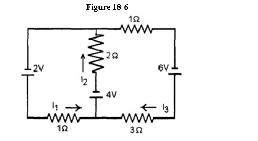
A) 6 - I1 - 2 I2 = 0
B) 4 - I1 + 4 I3 = 0
C) 2 - 2 I1 - 2 I2 - 4 I3 = 0
D) -2 - I1 - 2 I2 = 0
E) 2 - I1 - 2 I23 = 0
A) 6 - I1 - 2 I2 = 0
B) 4 - I1 + 4 I3 = 0
C) 2 - 2 I1 - 2 I2 - 4 I3 = 0
D) -2 - I1 - 2 I2 = 0
E) 2 - I1 - 2 I23 = 0
Question
In a wheatstone bridge (see Figure 18-7) the resistance  is varied until no current flows through the Galvanometer (G). Then one knows:
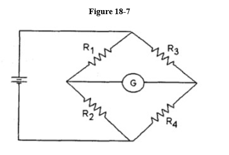
A) R1 - R2 = R3 - R4
B) R1 R4 = R2 R3
C) R1 / R4 = R3 / R2
D) R1 R2 = R3 R4
E) R1 + R2 = R3 + R4
is varied until no current flows through the Galvanometer (G). Then one knows: A) R1 - R2 = R3 - R4
B) R1 R4 = R2 R3
C) R1 / R4 = R3 / R2
D) R1 R2 = R3 R4
E) R1 + R2 = R3 + R4
Question
Question
Figure 18-8 is a symbol for which of the following?
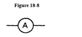
A) ammeter
B) galvanometer
C) voltmeter
D) resistor
E) fuse
A) ammeter
B) galvanometer
C) voltmeter
D) resistor
E) fuse
Question
Figure 18-9 is a symbol for which of the following?
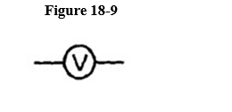
A) galvanometer
B) ammeter
C) fuse
D) ground
E) voltmeter
A) galvanometer
B) ammeter
C) fuse
D) ground
E) voltmeter
Question
Figure 18-10 is a symbol for which of the following?
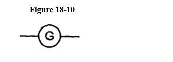
A) voltmeter
B) galvanometer
C) fuse
D) ammeter
E) ground
A) voltmeter
B) galvanometer
C) fuse
D) ammeter
E) ground
Question
Question
Question
Figure 18-11 is a symbol for which of the following?
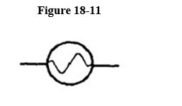
A) voltmeter
B) ammeter
C) galvanometer
D) resistor
E) fuse
A) voltmeter
B) ammeter
C) galvanometer
D) resistor
E) fuse
Question
One side of a normal outlet is at 120 V AC, the other side is at
A) -120 V AC.
B) +120 V AC.
C) 120 V AC.
V AC.
D) 0 V.
E) 240 V.
A) -120 V AC.
B) +120 V AC.
C) 120
V AC.D) 0 V.
E) 240 V.
Question
Question
Question
Question
Question
Question
Question
Question
Question
Question
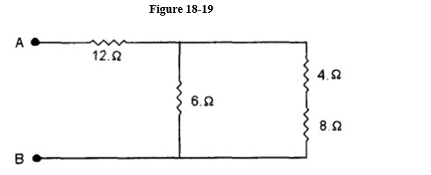
Find the equivalent resistance of the network shown in Figure 18-19 between points A and B:
Question
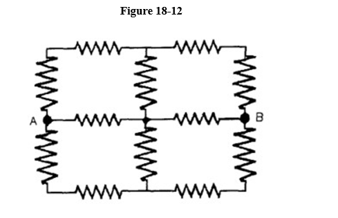
Determine the effective resistance between terminals A and B for the circuit shown in Figure 18-12. Each resistor is 10 ?.
Question
R1 = 5.6 , R2 = 5.6 , R3 = 14. , = 6.0 volts
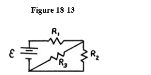
For the circuit shown in Figure 18-13 find:
(a) the total resistance connected to the battery.
(b) the current in each resistor.
For the circuit shown in Figure 18-13 find:
(a) the total resistance connected to the battery.
(b) the current in each resistor.
Question
Examine the circuit shown in Figure 18-14.
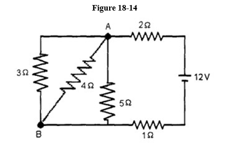
(a) Determine the current in each resistor.
(b) Determine the potential difference between points A and B.
(a) Determine the current in each resistor.
(b) Determine the potential difference between points A and B.
Question
See Figure 18-15. Given R1 = 18. , R2 = 44. , R3 = 33. , R4 = 14. , R5 = 12. , V1 = 18. volts, and V2 and 12.volts:
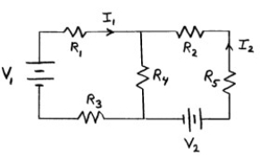
(a) determine I1.
(b) determine I2.
(a) determine I1.
(b) determine I2.
Question
See Figure 18-16. Given R1 = 50. , R2 = 20. , R3 = 35. , R4 = 10. , R5 = 68. , I1 and -.111 volts, and I2 - 0.142 volts:
(a) determine V1 and V2.
(b) determine the potential across R4.
(a) determine V1 and V2.
(b) determine the potential across R4.
Question
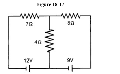
Determine the current and its direction, in each resistor, for the circuit shown in Figure 18-17.
Question
Question
A 40.0 F capacitor in series with a 5,000. resistor is charged by a 100. V battery. A neon lamp is connected cross the capacitor (in parallel with it). A neon lamp has a very high resistance before it "fires", i.e., ionizes. When the voltage across it reaches 70. V, it fires and its resistance drops almost instantaneously to zero. It then ceases to conduct once the voltage drops below 70. V. This results in periodically discharging the capacitor. This is the kind of circuit used to make roadside warning lights at construction sites.
Determine the frequency at which the light will blink in the Figure 18-18
Determine the frequency at which the light will blink in the Figure 18-18
Question
Question
Question
Question
Question
Question
Two 4.  resistors are connected in parallel, and this combination is connected in series with 3 https://storage.examlex.com/TB9720/11eea40a_3ec1_2e8d_97f4_ffd26a7d9b24_TB9720_11. What is the effective resistance of this combination?
A) 7. 11eea40a_3ec1_2e8d_97f4_ffd26a7d9b24_TB9720_11
B) 5. 11eea40a_3ec1_2e8d_97f4_ffd26a7d9b24_TB9720_11
C) 11. 11eea40a_3ec1_2e8d_97f4_ffd26a7d9b24_TB9720_11
D) 1.2 11eea40a_3ec1_2e8d_97f4_ffd26a7d9b24_TB9720_11
E) 4. 11eea40a_3ec1_2e8d_97f4_ffd26a7d9b24_TB9720_11
resistors are connected in parallel, and this combination is connected in series with 3 https://storage.examlex.com/TB9720/11eea40a_3ec1_2e8d_97f4_ffd26a7d9b24_TB9720_11. What is the effective resistance of this combination?A) 7. 11eea40a_3ec1_2e8d_97f4_ffd26a7d9b24_TB9720_11
B) 5. 11eea40a_3ec1_2e8d_97f4_ffd26a7d9b24_TB9720_11
C) 11. 11eea40a_3ec1_2e8d_97f4_ffd26a7d9b24_TB9720_11
D) 1.2 11eea40a_3ec1_2e8d_97f4_ffd26a7d9b24_TB9720_11
E) 4. 11eea40a_3ec1_2e8d_97f4_ffd26a7d9b24_TB9720_11
Question
A 3.0 resistor is connected in parallel with a 6.0 11eea40a_3ec1_2e8d_97f4_ffd26a7d9b24_TB9720_11resistor. This combination is connected in series with a 4.0 11eea40a_3ec1_2e8d_97f4_ffd26a7d9b24_TB9720_11 resistor. The resistors are connected to a 12. volt battery. How much power is dissipated in the 3.0 11eea40a_3ec1_2e8d_97f4_ffd26a7d9b24_TB9720_11 resistor?
A) 7.7 W
B) 6 W
C) 2.7 W
D) 12 W
E) 5.3 W
resistor is connected in parallel with a 6.0 11eea40a_3ec1_2e8d_97f4_ffd26a7d9b24_TB9720_11resistor. This combination is connected in series with a 4.0 11eea40a_3ec1_2e8d_97f4_ffd26a7d9b24_TB9720_11 resistor. The resistors are connected to a 12. volt battery. How much power is dissipated in the 3.0 11eea40a_3ec1_2e8d_97f4_ffd26a7d9b24_TB9720_11 resistor?A) 7.7 W
B) 6 W
C) 2.7 W
D) 12 W
E) 5.3 W
Question
A 6.0 and a 12.11eea40a_3ec1_2e8d_97f4_ffd26a7d9b24_TB9720_11resistor are connected in parallel to a 36. V battery. What power is dissipated by the 6.0 11eea40a_3ec1_2e8d_97f4_ffd26a7d9b24_TB9720_11 resistor?
A) 216.W
B) 48. W
C) 24. W
D) 12. W
E) 486. W
and a 12.11eea40a_3ec1_2e8d_97f4_ffd26a7d9b24_TB9720_11resistor are connected in parallel to a 36. V battery. What power is dissipated by the 6.0 11eea40a_3ec1_2e8d_97f4_ffd26a7d9b24_TB9720_11 resistor?A) 216.W
B) 48. W
C) 24. W
D) 12. W
E) 486. W
Question
A 6.0 and a 12. 11eea40a_3ec1_2e8d_97f4_ffd26a7d9b24_TB9720_11 resistor are connected in series to a 36. V battery. What power is dissipated by the 12.0 11eea40a_3ec1_2e8d_97f4_ffd26a7d9b24_TB9720_11 resistor?
A) 12. W
B) 486. W
C) 24. W
D) 48. W
E) 216. W
and a 12. 11eea40a_3ec1_2e8d_97f4_ffd26a7d9b24_TB9720_11 resistor are connected in series to a 36. V battery. What power is dissipated by the 12.0 11eea40a_3ec1_2e8d_97f4_ffd26a7d9b24_TB9720_11 resistor?A) 12. W
B) 486. W
C) 24. W
D) 48. W
E) 216. W
Question
Refer to the portion of a circuit given in Figure 18-20. What is the potential difference VA - VB if I = 5.0 Amperes?
A) 45. V
B) 55. V
C) 71. V
D) 35. V
E) 63. V
A) 45. V
B) 55. V
C) 71. V
D) 35. V
E) 63. V
Question
Shown in Figure 18-21 are a few segments of a circuit used to model an infinitely long transmission line. The circuit continues indefinitely in both directions.
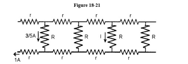
What is the value, in amperes, of the current I?
A) 12/125
B) 16/75
C) 8/125
D) 2/25
E) 4/25
What is the value, in amperes, of the current I?
A) 12/125
B) 16/75
C) 8/125
D) 2/25
E) 4/25
Question
Question
Question
A 2.0 F capacitor is charged through a 50,000.  resistor. How long does it take for the capacitor to reach 90% of full charge?
A) 2.19 s
B) 0.23 s
C) 2.3 s
D) 9.1 s
E) 0.9 s
resistor. How long does it take for the capacitor to reach 90% of full charge?A) 2.19 s
B) 0.23 s
C) 2.3 s
D) 9.1 s
E) 0.9 s
Question
A 4.0 F capacitor is charged to 6.0 V. It is then connected in series with a 3.0 M resistor and connected to a 12. V battery. How long after being connected to the battery will the voltage across the capacitor be 9.0 V?
A) 11. s
B) 5.5 s
C) 12. s
D) 8.3 s
E) 17. s
resistor and connected to a 12. V battery. How long after being connected to the battery will the voltage across the capacitor be 9.0 V?A) 11. s
B) 5.5 s
C) 12. s
D) 8.3 s
E) 17. s
Question
A 4.0 M resistor is connected in series with a 0.5 F capacitor. The capacitor is initially uncharged. The RC combination is charged by a 9.0 V battery. What is the change in voltage between t = RC and t = 3RC?
A) 11.4 V
B) 2.88 V
C) 8.81 V
D) 5.70 V
E) 7.59 V
resistor is connected in series with a 0.5 F capacitor. The capacitor is initially uncharged. The RC combination is charged by a 9.0 V battery. What is the change in voltage between t = RC and t = 3RC?A) 11.4 V
B) 2.88 V
C) 8.81 V
D) 5.70 V
E) 7.59 V
Question
A galvanometer with a coil resistance of 80.  deflects full scale for a current of 2.00 mA. What series resistance is required to convert it to a voltmeter reading full scale for 200. V?
A) 100.02 k11eea40a_e302_9700_97f4_89f651598bd8_TB9720_11
B) 0.800 m11eea40a_e302_9700_97f4_89f651598bd8_TB9720_11
C) 13.2 M11eea40a_e302_9700_97f4_89f651598bd8_TB9720_11
D) 100. k11eea40a_e302_9700_97f4_89f651598bd8_TB9720_11
E) 99.92 k11eea40a_e302_9700_97f4_89f651598bd8_TB9720_11
deflects full scale for a current of 2.00 mA. What series resistance is required to convert it to a voltmeter reading full scale for 200. V?A) 100.02 k11eea40a_e302_9700_97f4_89f651598bd8_TB9720_11
B) 0.800 m11eea40a_e302_9700_97f4_89f651598bd8_TB9720_11
C) 13.2 M11eea40a_e302_9700_97f4_89f651598bd8_TB9720_11
D) 100. k11eea40a_e302_9700_97f4_89f651598bd8_TB9720_11
E) 99.92 k11eea40a_e302_9700_97f4_89f651598bd8_TB9720_11
Question

Unlock Deck
Sign up to unlock the cards in this deck!
Unlock Deck
Unlock Deck
1/68
Play
Full screen (f)
Deck 18: Basic Electric Circuits
1
State Kirchhoff's junction theorem.
The algebraic sum of the currents at any junction is zero.
2
State Kirchhoff's loop theorem.
The algebraic sum of the potential differences across all the elements of any closed loop is zero.
3
For the circuit illustrated in Figure 18-1, write the Kirchhoff current equation for the node labeled A.
I1 - I2 + I3 = 0
4
Write the Kirchhoff loop equation for the entire outside loop (see Figure 18-2)
Unlock Deck
Unlock for access to all 68 flashcards in this deck.
Unlock Deck
k this deck
5
See Figure 18-3. Write the Kirchhoff loop equation for the:
(a) left hand loop in terms of V1, V2, R1, R2, R3, R4, R5, I1 and I2.
(b) right hand loop in terms of V1, V2, R1, R2, R3, R4, R5, I1 and I2.
(a) left hand loop in terms of V1, V2, R1, R2, R3, R4, R5, I1 and I2.
(b) right hand loop in terms of V1, V2, R1, R2, R3, R4, R5, I1 and I2.
Unlock Deck
Unlock for access to all 68 flashcards in this deck.
Unlock Deck
k this deck
6
When charging a capacitor with a battery, how would the internal resistance of the battery affect the charging of the capacitor?
Unlock Deck
Unlock for access to all 68 flashcards in this deck.
Unlock Deck
k this deck
7
Why aren't houses wired with outlets in series instead of in parallel?
Unlock Deck
Unlock for access to all 68 flashcards in this deck.
Unlock Deck
k this deck
8
Usually one can touch the terminals of a battery (e.g. 1.5 volts) to equipment in order to guard against the presence of low potentials? (i.e., why are low voltages hazardous in hospitals?)
Unlock Deck
Unlock for access to all 68 flashcards in this deck.
Unlock Deck
k this deck
9
Why do power tools with a plastic case not have a 3-prong plug but metal encased tools have (or should have) 3-prong plugs?
Unlock Deck
Unlock for access to all 68 flashcards in this deck.
Unlock Deck
k this deck
10
When resistors are connected in parallel to a source of emf, the current through each resistor is the same.
Unlock Deck
Unlock for access to all 68 flashcards in this deck.
Unlock Deck
k this deck
11
In a polarized plug, the large slit connects to the hot side and the small slit connects to the neutral, or ground, side.
Unlock Deck
Unlock for access to all 68 flashcards in this deck.
Unlock Deck
k this deck
12
When resistors are connected in series
A) the same power is dissipated in each one.
B) the total effective resistance is reduced.
C) the current flowing in each is the same.
D) the potential difference across each is the same.
A) the same power is dissipated in each one.
B) the total effective resistance is reduced.
C) the current flowing in each is the same.
D) the potential difference across each is the same.
Unlock Deck
Unlock for access to all 68 flashcards in this deck.
Unlock Deck
k this deck
13
When two or more resistors are connected in parallel to a battery
A) the total current flowing from the battery equals the sum of the currents flowing through each resistor.
B) the equivalent resistance of the combination is less than the resistance of any one of the resistors.
C) the voltage across each resistor is the same.
D) all of the other choices are true.
A) the total current flowing from the battery equals the sum of the currents flowing through each resistor.
B) the equivalent resistance of the combination is less than the resistance of any one of the resistors.
C) the voltage across each resistor is the same.
D) all of the other choices are true.
Unlock Deck
Unlock for access to all 68 flashcards in this deck.
Unlock Deck
k this deck
14
When two or more resistors are connected in series to a battery
A) the same current flows through each resistor.
B) the total voltage across the combination is the algebraic sum of the voltages across the individual resistors.
C) the equivalent resistance of the combination is equal to the sum of the resistances of each resistor.
D) all of the other choices are true.
Unlock Deck
Unlock for access to all 68 flashcards in this deck.
Unlock Deck
k this deck
15
As more resistors are added in series to a constant voltage source (zero internal resistance), the power supplied by the source
A) does not change.
B) increases for a time and then starts to decrease.
C) decreases.
D) increases.
A) does not change.
B) increases for a time and then starts to decrease.
C) decreases.
D) increases.
Unlock Deck
Unlock for access to all 68 flashcards in this deck.
Unlock Deck
k this deck
16
You obtain a 100. W lightbulb and a 50. W light bulb. Instead of connecting them in the normal way, you devise a circuit that places them in series across normal household voltage. Which statement is correct?
A) The 50-W bulb glows more brightly than the 100-W bulb.
B) The 100-W bulb glows brighter than the 50-W bulb.
C) Both bulbs glow at the same reduced brightness.
D) Both bulbs glow at the same increased brightness.
A) The 50-W bulb glows more brightly than the 100-W bulb.
B) The 100-W bulb glows brighter than the 50-W bulb.
C) Both bulbs glow at the same reduced brightness.
D) Both bulbs glow at the same increased brightness.
Unlock Deck
Unlock for access to all 68 flashcards in this deck.
Unlock Deck
k this deck
17
A 3. resistor is connected in parallel with a 6. 11eea409_b6c6_d93c_97f4_a5754f0dddc8_TB9720_11 resistor. This pair is then connected in series with a 4. 11eea409_b6c6_d93c_97f4_a5754f0dddc8_TB9720_11 resistor. These resistors are connected to a battery. What will happen if the 3. 11eea409_b6c6_d93c_97f4_a5754f0dddc8_TB9720_11 resistor burns out, i.e., becomes an infinite resistance?
A) The power dissipated in the circuit will increase.
B) The current in the 6. 11eea409_b6c6_d93c_97f4_a5754f0dddc8_TB9720_11 resistor will increase.
C) The current provided by the battery will not change.
D) The current in the 4. 11eea409_b6c6_d93c_97f4_a5754f0dddc8_TB9720_11 resistor will drop to zero.
resistor is connected in parallel with a 6. 11eea409_b6c6_d93c_97f4_a5754f0dddc8_TB9720_11 resistor. This pair is then connected in series with a 4. 11eea409_b6c6_d93c_97f4_a5754f0dddc8_TB9720_11 resistor. These resistors are connected to a battery. What will happen if the 3. 11eea409_b6c6_d93c_97f4_a5754f0dddc8_TB9720_11 resistor burns out, i.e., becomes an infinite resistance?A) The power dissipated in the circuit will increase.
B) The current in the 6. 11eea409_b6c6_d93c_97f4_a5754f0dddc8_TB9720_11 resistor will increase.
C) The current provided by the battery will not change.
D) The current in the 4. 11eea409_b6c6_d93c_97f4_a5754f0dddc8_TB9720_11 resistor will drop to zero.
Unlock Deck
Unlock for access to all 68 flashcards in this deck.
Unlock Deck
k this deck
18
Consider three identical resistors, each of resistance R. The maximum power each can dissipate is P. Two of the resistors are connected in series, and a third is connected in parallel with these two. What is the maximum power this network can dissipate?
A) 2P/3
B) 3P
C) 2P
D) 3P/2
E) P
A) 2P/3
B) 3P
C) 2P
D) 3P/2
E) P
Unlock Deck
Unlock for access to all 68 flashcards in this deck.
Unlock Deck
k this deck
19
Kirchhoff's junction rule is an example of
A) conservation of charge.
B) conservation of energy.
C) conservation of momentum.
D) conservation of energy and momentum.
A) conservation of charge.
B) conservation of energy.
C) conservation of momentum.
D) conservation of energy and momentum.
Unlock Deck
Unlock for access to all 68 flashcards in this deck.
Unlock Deck
k this deck
20
Kirchhoff's voltage rule for a closed loop is an example of
A) conservation of energy.
B) conservation of charge.
C) conservation of force.
D) conservation of momentum.
A) conservation of energy.
B) conservation of charge.
C) conservation of force.
D) conservation of momentum.
Unlock Deck
Unlock for access to all 68 flashcards in this deck.
Unlock Deck
k this deck
21
In Figure 18-4, which of the following equations is true?
A) V1 - I1 R1 - I2 R2 + V2 - I2 R3 = 0
B) V1 + I1 R1 - I2 R2 - V2 - I3 R4 = 0
C) V1 - I1 R1 + I2 R2 - V2 + I2 R3 = 0
D) V1 I1 R1 + I2 R2 + V2 + I2 R3 = 0
A) V1 - I1 R1 - I2 R2 + V2 - I2 R3 = 0
B) V1 + I1 R1 - I2 R2 - V2 - I3 R4 = 0
C) V1 - I1 R1 + I2 R2 - V2 + I2 R3 = 0
D) V1 I1 R1 + I2 R2 + V2 + I2 R3 = 0
Unlock Deck
Unlock for access to all 68 flashcards in this deck.
Unlock Deck
k this deck
22
In Figure 18-5, which of the following relations is true?
A) I1 + I2 - I3 = 0
B) I1- I2 - I3 = 0
C) I1- I2 + I3 = 0
D) - I1 + I2 + I3 = 0
E) I1+ I2 + I3 = 0
A) I1 + I2 - I3 = 0
B) I1- I2 - I3 = 0
C) I1- I2 + I3 = 0
D) - I1 + I2 + I3 = 0
E) I1+ I2 + I3 = 0
Unlock Deck
Unlock for access to all 68 flashcards in this deck.
Unlock Deck
k this deck
23
Which of the equations here is valid for the circuit shown in Figure 18-6?
A) 6 - I1 - 2 I2 = 0
B) 4 - I1 + 4 I3 = 0
C) 2 - 2 I1 - 2 I2 - 4 I3 = 0
D) -2 - I1 - 2 I2 = 0
E) 2 - I1 - 2 I23 = 0
A) 6 - I1 - 2 I2 = 0
B) 4 - I1 + 4 I3 = 0
C) 2 - 2 I1 - 2 I2 - 4 I3 = 0
D) -2 - I1 - 2 I2 = 0
E) 2 - I1 - 2 I23 = 0
Unlock Deck
Unlock for access to all 68 flashcards in this deck.
Unlock Deck
k this deck
24
In a wheatstone bridge (see Figure 18-7) the resistance is varied until no current flows through the Galvanometer (G). Then one knows:
A) R1 - R2 = R3 - R4
B) R1 R4 = R2 R3
C) R1 / R4 = R3 / R2
D) R1 R2 = R3 R4
E) R1 + R2 = R3 + R4
is varied until no current flows through the Galvanometer (G). Then one knows: A) R1 - R2 = R3 - R4
B) R1 R4 = R2 R3
C) R1 / R4 = R3 / R2
D) R1 R2 = R3 R4
E) R1 + R2 = R3 + R4
Unlock Deck
Unlock for access to all 68 flashcards in this deck.
Unlock Deck
k this deck
25
What is the unit for the quantity RC?
A) seconds
B) volt-Ampere/ohm
C) meters
D) Kg
E) ohms
A) seconds
B) volt-Ampere/ohm
C) meters
D) Kg
E) ohms
Unlock Deck
Unlock for access to all 68 flashcards in this deck.
Unlock Deck
k this deck
26
Figure 18-8 is a symbol for which of the following?
A) ammeter
B) galvanometer
C) voltmeter
D) resistor
E) fuse
A) ammeter
B) galvanometer
C) voltmeter
D) resistor
E) fuse
Unlock Deck
Unlock for access to all 68 flashcards in this deck.
Unlock Deck
k this deck
27
Figure 18-9 is a symbol for which of the following?
A) galvanometer
B) ammeter
C) fuse
D) ground
E) voltmeter
A) galvanometer
B) ammeter
C) fuse
D) ground
E) voltmeter
Unlock Deck
Unlock for access to all 68 flashcards in this deck.
Unlock Deck
k this deck
28
Figure 18-10 is a symbol for which of the following?
A) voltmeter
B) galvanometer
C) fuse
D) ammeter
E) ground
A) voltmeter
B) galvanometer
C) fuse
D) ammeter
E) ground
Unlock Deck
Unlock for access to all 68 flashcards in this deck.
Unlock Deck
k this deck
29
Increasing the resistance of a voltmeter's series resistance
A) converts it to an ammeter.
B) allows it to measure a larger voltage at full-scale deflection.
C) allows it to measure a smaller voltage at full-scale deflection.
D) enables more current to pass through the meter movement at full-scale deflection.
A) converts it to an ammeter.
B) allows it to measure a larger voltage at full-scale deflection.
C) allows it to measure a smaller voltage at full-scale deflection.
D) enables more current to pass through the meter movement at full-scale deflection.
Unlock Deck
Unlock for access to all 68 flashcards in this deck.
Unlock Deck
k this deck
30
An unknown resistor is wired in series and an ammeter and a voltmeter are placed in parallel across both the resistor and the ammeter. This network is then placed across a battery. If one computes the value of the resistance by dividing the voltmeter reading by the ammeter reading, the value obtained
A) is the true resistance.
B) could be anything. It depends on other factors.
C) is less than the true resistance.
D) is greater than the true resistance.
A) is the true resistance.
B) could be anything. It depends on other factors.
C) is less than the true resistance.
D) is greater than the true resistance.
Unlock Deck
Unlock for access to all 68 flashcards in this deck.
Unlock Deck
k this deck
31
Figure 18-11 is a symbol for which of the following?
A) voltmeter
B) ammeter
C) galvanometer
D) resistor
E) fuse
A) voltmeter
B) ammeter
C) galvanometer
D) resistor
E) fuse
Unlock Deck
Unlock for access to all 68 flashcards in this deck.
Unlock Deck
k this deck
32
One side of a normal outlet is at 120 V AC, the other side is at
A) -120 V AC.
B) +120 V AC.
C) 120 V AC.
D) 0 V.
E) 240 V.
A) -120 V AC.
B) +120 V AC.
C) 120
V AC.D) 0 V.
E) 240 V.
Unlock Deck
Unlock for access to all 68 flashcards in this deck.
Unlock Deck
k this deck
33
The usual household fuse or circuit breaker is rated at
A) 150 A.
B) 15 A.
C) 1.5 A.
D) 15 mA.
E) 150 mA.
A) 150 A.
B) 15 A.
C) 1.5 A.
D) 15 mA.
E) 150 mA.
Unlock Deck
Unlock for access to all 68 flashcards in this deck.
Unlock Deck
k this deck
34
The minimum current that will usually kill the average person is
A) 10. A.
B) 0.1 mA.
C) 1. A.
D) 0.01 A.
E) 0.1 A.
A) 10. A.
B) 0.1 mA.
C) 1. A.
D) 0.01 A.
E) 0.1 A.
Unlock Deck
Unlock for access to all 68 flashcards in this deck.
Unlock Deck
k this deck
35
Current just enough to cause ventricular fibrillation is
A) 1. mA.
B) 1. A.
C) 10. mA.
D) 100. mA.
E) 10. A.
A) 1. mA.
B) 1. A.
C) 10. mA.
D) 100. mA.
E) 10. A.
Unlock Deck
Unlock for access to all 68 flashcards in this deck.
Unlock Deck
k this deck
36
A polarized plug
A) has 3 prongs.
B) is asymmetrical.
C) is a grounded plug.
D) may be reversed.
A) has 3 prongs.
B) is asymmetrical.
C) is a grounded plug.
D) may be reversed.
Unlock Deck
Unlock for access to all 68 flashcards in this deck.
Unlock Deck
k this deck
37
The dedicated 3rd wire on a 3 prong plug is connected to
A) ground.
B) a ground fault interrupter.
C) the "hot" wire.
D) a fuse.
A) ground.
B) a ground fault interrupter.
C) the "hot" wire.
D) a fuse.
Unlock Deck
Unlock for access to all 68 flashcards in this deck.
Unlock Deck
k this deck
38
A "blown" fuse has
A) infinite (very large) resistance.
B) moderate resistance.
C) zero resistance.
A) infinite (very large) resistance.
B) moderate resistance.
C) zero resistance.
Unlock Deck
Unlock for access to all 68 flashcards in this deck.
Unlock Deck
k this deck
39
What different resistances can be obtained by using two 2. resistors and
one 4. resistor?
one 4. resistor?
Unlock Deck
Unlock for access to all 68 flashcards in this deck.
Unlock Deck
k this deck
40
A combination of 2.0 in series with 4.0 is connected in parallel with 3.0 . What is the equivalent resistance?
Unlock Deck
Unlock for access to all 68 flashcards in this deck.
Unlock Deck
k this deck
41
What resistance added to 633. in parallel would produce an equivalent 205. ?
Unlock Deck
Unlock for access to all 68 flashcards in this deck.
Unlock Deck
k this deck
42
Find the equivalent resistance of the network shown in Figure 18-19 between points A and B:
Unlock Deck
Unlock for access to all 68 flashcards in this deck.
Unlock Deck
k this deck
43
Determine the effective resistance between terminals A and B for the circuit shown in Figure 18-12. Each resistor is 10 ?.
Unlock Deck
Unlock for access to all 68 flashcards in this deck.
Unlock Deck
k this deck
44
R1 = 5.6 , R2 = 5.6 , R3 = 14. , = 6.0 volts
For the circuit shown in Figure 18-13 find:
(a) the total resistance connected to the battery.
(b) the current in each resistor.
For the circuit shown in Figure 18-13 find:
(a) the total resistance connected to the battery.
(b) the current in each resistor.
Unlock Deck
Unlock for access to all 68 flashcards in this deck.
Unlock Deck
k this deck
45
Examine the circuit shown in Figure 18-14.
(a) Determine the current in each resistor.
(b) Determine the potential difference between points A and B.
(a) Determine the current in each resistor.
(b) Determine the potential difference between points A and B.
Unlock Deck
Unlock for access to all 68 flashcards in this deck.
Unlock Deck
k this deck
46
See Figure 18-15. Given R1 = 18. , R2 = 44. , R3 = 33. , R4 = 14. , R5 = 12. , V1 = 18. volts, and V2 and 12.volts:
(a) determine I1.
(b) determine I2.
(a) determine I1.
(b) determine I2.
Unlock Deck
Unlock for access to all 68 flashcards in this deck.
Unlock Deck
k this deck
47
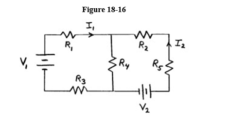
See Figure 18-16. Given R1 = 50. , R2 = 20. , R3 = 35. , R4 = 10. , R5 = 68. , I1 and -.111 volts, and I2 - 0.142 volts:
(a) determine V1 and V2.
(b) determine the potential across R4.
(a) determine V1 and V2.
(b) determine the potential across R4.
Unlock Deck
Unlock for access to all 68 flashcards in this deck.
Unlock Deck
k this deck
48
Determine the current and its direction, in each resistor, for the circuit shown in Figure 18-17.
Unlock Deck
Unlock for access to all 68 flashcards in this deck.
Unlock Deck
k this deck
49
An RC circuit with 2.50 F and 7.60 M? includes a 6.00 volt source.
(a) What is the time constant for charging the capacitor?
(b) What voltage is across the capacitor 25. s after charging begins?
(a) What is the time constant for charging the capacitor?
(b) What voltage is across the capacitor 25. s after charging begins?
Unlock Deck
Unlock for access to all 68 flashcards in this deck.
Unlock Deck
k this deck
50
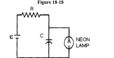
A 40.0 F capacitor in series with a 5,000. resistor is charged by a 100. V battery. A neon lamp is connected cross the capacitor (in parallel with it). A neon lamp has a very high resistance before it "fires", i.e., ionizes. When the voltage across it reaches 70. V, it fires and its resistance drops almost instantaneously to zero. It then ceases to conduct once the voltage drops below 70. V. This results in periodically discharging the capacitor. This is the kind of circuit used to make roadside warning lights at construction sites.
Determine the frequency at which the light will blink in the Figure 18-18
Determine the frequency at which the light will blink in the Figure 18-18
Unlock Deck
Unlock for access to all 68 flashcards in this deck.
Unlock Deck
k this deck
51
A galvanometer with a coil resistance of 40. deflects full scale for a current of 2.0 mA. What series resistance should be used with this galvanometer in order to construct a voltmeter that deflects full scale for 50. V?
Unlock Deck
Unlock for access to all 68 flashcards in this deck.
Unlock Deck
k this deck
52
A 150. A full scale galvanometer is used as a 1.00 A full scale ammeter when shunted by 3.3 m . What is the coil resistance of the galvanometer?
Unlock Deck
Unlock for access to all 68 flashcards in this deck.
Unlock Deck
k this deck
53
A galvanometer has a coil with a resistance of 24. . A current of 180. A causes full-scale deflection. If the galvanometer is to be used to construct an ammeter that deflects full scale for 10.0 A, what shunt resistor is required?
Unlock Deck
Unlock for access to all 68 flashcards in this deck.
Unlock Deck
k this deck
54
Consider a galvanometer with full scale sensitivity of 333. A and a coil resistance of 33. .
(a) What shunt resistance is needed to make a 5.0 A ammeter?
(b) What series resistance is needed to construct a 5.0 volt voltmeter?
(a) What shunt resistance is needed to make a 5.0 A ammeter?
(b) What series resistance is needed to construct a 5.0 volt voltmeter?
Unlock Deck
Unlock for access to all 68 flashcards in this deck.
Unlock Deck
k this deck
55
Three identical resistors are connected in series to a 12-V battery. What is the voltage across any one of the resistors?
A) 0 V
B) 36 V
C) 4 V
D) 3 V
E) 12 V
A) 0 V
B) 36 V
C) 4 V
D) 3 V
E) 12 V
Unlock Deck
Unlock for access to all 68 flashcards in this deck.
Unlock Deck
k this deck
56
Two 4. resistors are connected in parallel, and this combination is connected in series with 3 https://storage.examlex.com/TB9720/11eea40a_3ec1_2e8d_97f4_ffd26a7d9b24_TB9720_11. What is the effective resistance of this combination?
A) 7. 11eea40a_3ec1_2e8d_97f4_ffd26a7d9b24_TB9720_11
B) 5. 11eea40a_3ec1_2e8d_97f4_ffd26a7d9b24_TB9720_11
C) 11. 11eea40a_3ec1_2e8d_97f4_ffd26a7d9b24_TB9720_11
D) 1.2 11eea40a_3ec1_2e8d_97f4_ffd26a7d9b24_TB9720_11
E) 4. 11eea40a_3ec1_2e8d_97f4_ffd26a7d9b24_TB9720_11
resistors are connected in parallel, and this combination is connected in series with 3 https://storage.examlex.com/TB9720/11eea40a_3ec1_2e8d_97f4_ffd26a7d9b24_TB9720_11. What is the effective resistance of this combination?A) 7. 11eea40a_3ec1_2e8d_97f4_ffd26a7d9b24_TB9720_11
B) 5. 11eea40a_3ec1_2e8d_97f4_ffd26a7d9b24_TB9720_11
C) 11. 11eea40a_3ec1_2e8d_97f4_ffd26a7d9b24_TB9720_11
D) 1.2 11eea40a_3ec1_2e8d_97f4_ffd26a7d9b24_TB9720_11
E) 4. 11eea40a_3ec1_2e8d_97f4_ffd26a7d9b24_TB9720_11
Unlock Deck
Unlock for access to all 68 flashcards in this deck.
Unlock Deck
k this deck
57
A 3.0 resistor is connected in parallel with a 6.0 11eea40a_3ec1_2e8d_97f4_ffd26a7d9b24_TB9720_11resistor. This combination is connected in series with a 4.0 11eea40a_3ec1_2e8d_97f4_ffd26a7d9b24_TB9720_11 resistor. The resistors are connected to a 12. volt battery. How much power is dissipated in the 3.0 11eea40a_3ec1_2e8d_97f4_ffd26a7d9b24_TB9720_11 resistor?
A) 7.7 W
B) 6 W
C) 2.7 W
D) 12 W
E) 5.3 W
resistor is connected in parallel with a 6.0 11eea40a_3ec1_2e8d_97f4_ffd26a7d9b24_TB9720_11resistor. This combination is connected in series with a 4.0 11eea40a_3ec1_2e8d_97f4_ffd26a7d9b24_TB9720_11 resistor. The resistors are connected to a 12. volt battery. How much power is dissipated in the 3.0 11eea40a_3ec1_2e8d_97f4_ffd26a7d9b24_TB9720_11 resistor?A) 7.7 W
B) 6 W
C) 2.7 W
D) 12 W
E) 5.3 W
Unlock Deck
Unlock for access to all 68 flashcards in this deck.
Unlock Deck
k this deck
58
A 6.0 and a 12.11eea40a_3ec1_2e8d_97f4_ffd26a7d9b24_TB9720_11resistor are connected in parallel to a 36. V battery. What power is dissipated by the 6.0 11eea40a_3ec1_2e8d_97f4_ffd26a7d9b24_TB9720_11 resistor?
A) 216.W
B) 48. W
C) 24. W
D) 12. W
E) 486. W
and a 12.11eea40a_3ec1_2e8d_97f4_ffd26a7d9b24_TB9720_11resistor are connected in parallel to a 36. V battery. What power is dissipated by the 6.0 11eea40a_3ec1_2e8d_97f4_ffd26a7d9b24_TB9720_11 resistor?A) 216.W
B) 48. W
C) 24. W
D) 12. W
E) 486. W
Unlock Deck
Unlock for access to all 68 flashcards in this deck.
Unlock Deck
k this deck
59
A 6.0 and a 12. 11eea40a_3ec1_2e8d_97f4_ffd26a7d9b24_TB9720_11 resistor are connected in series to a 36. V battery. What power is dissipated by the 12.0 11eea40a_3ec1_2e8d_97f4_ffd26a7d9b24_TB9720_11 resistor?
A) 12. W
B) 486. W
C) 24. W
D) 48. W
E) 216. W
and a 12. 11eea40a_3ec1_2e8d_97f4_ffd26a7d9b24_TB9720_11 resistor are connected in series to a 36. V battery. What power is dissipated by the 12.0 11eea40a_3ec1_2e8d_97f4_ffd26a7d9b24_TB9720_11 resistor?A) 12. W
B) 486. W
C) 24. W
D) 48. W
E) 216. W
Unlock Deck
Unlock for access to all 68 flashcards in this deck.
Unlock Deck
k this deck
60
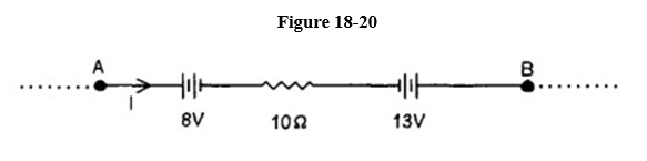
Refer to the portion of a circuit given in Figure 18-20. What is the potential difference VA - VB if I = 5.0 Amperes?
A) 45. V
B) 55. V
C) 71. V
D) 35. V
E) 63. V
A) 45. V
B) 55. V
C) 71. V
D) 35. V
E) 63. V
Unlock Deck
Unlock for access to all 68 flashcards in this deck.
Unlock Deck
k this deck
61
Shown in Figure 18-21 are a few segments of a circuit used to model an infinitely long transmission line. The circuit continues indefinitely in both directions.
What is the value, in amperes, of the current I?
A) 12/125
B) 16/75
C) 8/125
D) 2/25
E) 4/25
What is the value, in amperes, of the current I?
A) 12/125
B) 16/75
C) 8/125
D) 2/25
E) 4/25
Unlock Deck
Unlock for access to all 68 flashcards in this deck.
Unlock Deck
k this deck
62
A fully charged capacitor (37. F) is discharged through a resistor (1000. ohms). If the voltage reduced to 7.6 volts after just 20. ms, what was the original potential on the capacitor?
A) 16. volts
B) 13. volts
C) 11. volts
D) 9.0 volts
E) 8.0 volts
A) 16. volts
B) 13. volts
C) 11. volts
D) 9.0 volts
E) 8.0 volts
Unlock Deck
Unlock for access to all 68 flashcards in this deck.
Unlock Deck
k this deck
63
A 1234. pF capacitor and a 5.6 × 10⁶ ohm resistor are connected in series to 78. volts EMF. Approximately how long does it take the capacitor to become almost fully charged?
A) 0.1 ms
B) 1. s
C) 0.01 s
D) 1. ps
E) 1. s
A) 0.1 ms
B) 1. s
C) 0.01 s
D) 1. ps
E) 1. s
Unlock Deck
Unlock for access to all 68 flashcards in this deck.
Unlock Deck
k this deck
64
A 2.0 F capacitor is charged through a 50,000. resistor. How long does it take for the capacitor to reach 90% of full charge?
A) 2.19 s
B) 0.23 s
C) 2.3 s
D) 9.1 s
E) 0.9 s
resistor. How long does it take for the capacitor to reach 90% of full charge?A) 2.19 s
B) 0.23 s
C) 2.3 s
D) 9.1 s
E) 0.9 s
Unlock Deck
Unlock for access to all 68 flashcards in this deck.
Unlock Deck
k this deck
65
A 4.0 F capacitor is charged to 6.0 V. It is then connected in series with a 3.0 M resistor and connected to a 12. V battery. How long after being connected to the battery will the voltage across the capacitor be 9.0 V?
A) 11. s
B) 5.5 s
C) 12. s
D) 8.3 s
E) 17. s
resistor and connected to a 12. V battery. How long after being connected to the battery will the voltage across the capacitor be 9.0 V?A) 11. s
B) 5.5 s
C) 12. s
D) 8.3 s
E) 17. s
Unlock Deck
Unlock for access to all 68 flashcards in this deck.
Unlock Deck
k this deck
66
A 4.0 M resistor is connected in series with a 0.5 F capacitor. The capacitor is initially uncharged. The RC combination is charged by a 9.0 V battery. What is the change in voltage between t = RC and t = 3RC?
A) 11.4 V
B) 2.88 V
C) 8.81 V
D) 5.70 V
E) 7.59 V
resistor is connected in series with a 0.5 F capacitor. The capacitor is initially uncharged. The RC combination is charged by a 9.0 V battery. What is the change in voltage between t = RC and t = 3RC?A) 11.4 V
B) 2.88 V
C) 8.81 V
D) 5.70 V
E) 7.59 V
Unlock Deck
Unlock for access to all 68 flashcards in this deck.
Unlock Deck
k this deck
67
A galvanometer with a coil resistance of 80. deflects full scale for a current of 2.00 mA. What series resistance is required to convert it to a voltmeter reading full scale for 200. V?
A) 100.02 k11eea40a_e302_9700_97f4_89f651598bd8_TB9720_11
B) 0.800 m11eea40a_e302_9700_97f4_89f651598bd8_TB9720_11
C) 13.2 M11eea40a_e302_9700_97f4_89f651598bd8_TB9720_11
D) 100. k11eea40a_e302_9700_97f4_89f651598bd8_TB9720_11
E) 99.92 k11eea40a_e302_9700_97f4_89f651598bd8_TB9720_11
deflects full scale for a current of 2.00 mA. What series resistance is required to convert it to a voltmeter reading full scale for 200. V?A) 100.02 k11eea40a_e302_9700_97f4_89f651598bd8_TB9720_11
B) 0.800 m11eea40a_e302_9700_97f4_89f651598bd8_TB9720_11
C) 13.2 M11eea40a_e302_9700_97f4_89f651598bd8_TB9720_11
D) 100. k11eea40a_e302_9700_97f4_89f651598bd8_TB9720_11
E) 99.92 k11eea40a_e302_9700_97f4_89f651598bd8_TB9720_11
Unlock Deck
Unlock for access to all 68 flashcards in this deck.
Unlock Deck
k this deck
68
My electric razor operates on 120. v and requires 3.0 Amperes. How much current comes out after delivering 360. watts of power?
A) 2.4 A
B) 3.0 A
C) 0. A
D) 40. A
E) 1.2 A
A) 2.4 A
B) 3.0 A
C) 0. A
D) 40. A
E) 1.2 A
Unlock Deck
Unlock for access to all 68 flashcards in this deck.
Unlock Deck
k this deck
Unlock Deck
Unlock for access to all 68 flashcards in this deck.


