Deck 2: Power Transformers
Full screen (f)
Question
Question
Question
Question
The following data are obtained when open-circuit and short-circuit tests are performed on a single-phase, , distribution transformer.
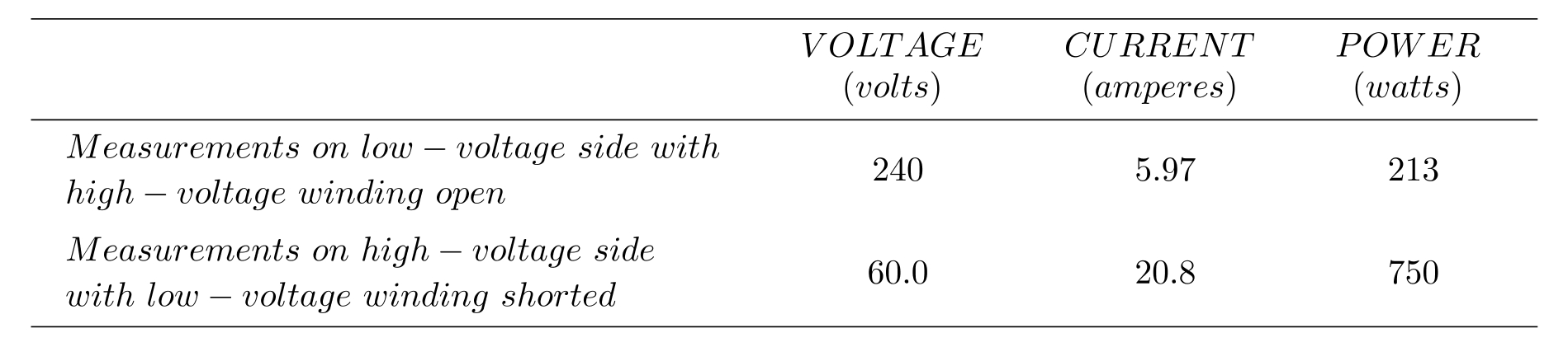
(a) Neglecting the series impedance, determine the exciting admittance referred to the high-voltage side. (b) Neglecting the exciting admittance, determine the equivalent series impedance referred to the high-voltage side. (c) Assuming equal series impedances for the primary and referred secondary, obtain an equivalent T-circuit referred to the high-voltage side.
(a) Neglecting the series impedance, determine the exciting admittance referred to the high-voltage side. (b) Neglecting the exciting admittance, determine the equivalent series impedance referred to the high-voltage side. (c) Assuming equal series impedances for the primary and referred secondary, obtain an equivalent T-circuit referred to the high-voltage side.
Question
Question
Question
Question
Question
Question
Question
Consider the single-line diagram of the power system shown in Figure P3.11. Equipment rating are:}
Neglecting resistance, transformer phase shift, and magnetizing reactance, draw the equivalent reactance diagram. Use a base of and for the 40 -ohm line. Determine the per-unit reactances.
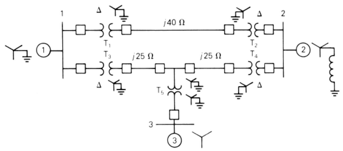
FIGURE P3.11
Neglecting resistance, transformer phase shift, and magnetizing reactance, draw the equivalent reactance diagram. Use a base of and for the 40 -ohm line. Determine the per-unit reactances.
FIGURE P3.11
Question
Question
Question
Question
Figure P3.15 shows a one-line diagram of a system in which the three-phase generator is rated 300 MVA, with a subtransient reactance of 0.2 per unit and with its neutral grounded through a reactor. The transmission line is long with a series reactance of . The three-phase transformer is rated with a leakage reactance of 0.1 per unit. Transformer is composed of three single-phase transformers, each rated with a leakage reactance of 0.1 per unit. Two motors and with a subtransient reactance of 0.2 per unit for each motor represent the load. has a rated input of 200 MVA with its neutral grounded through a current-limiting reactor. has a rated input of 100 MVA with its neutral not connected to ground. Neglect phase shifts associated with the transformers. Choose the generator rating as base in the generator circuit and draw the positive-sequence reactance diagram showing all reactances in per unit.
Figure P3.15
Figure P3.15
Question
Question
Question

Unlock Deck
Sign up to unlock the cards in this deck!
Unlock Deck
Unlock Deck
1/18
Play
Full screen (f)
Deck 2: Power Transformers
1
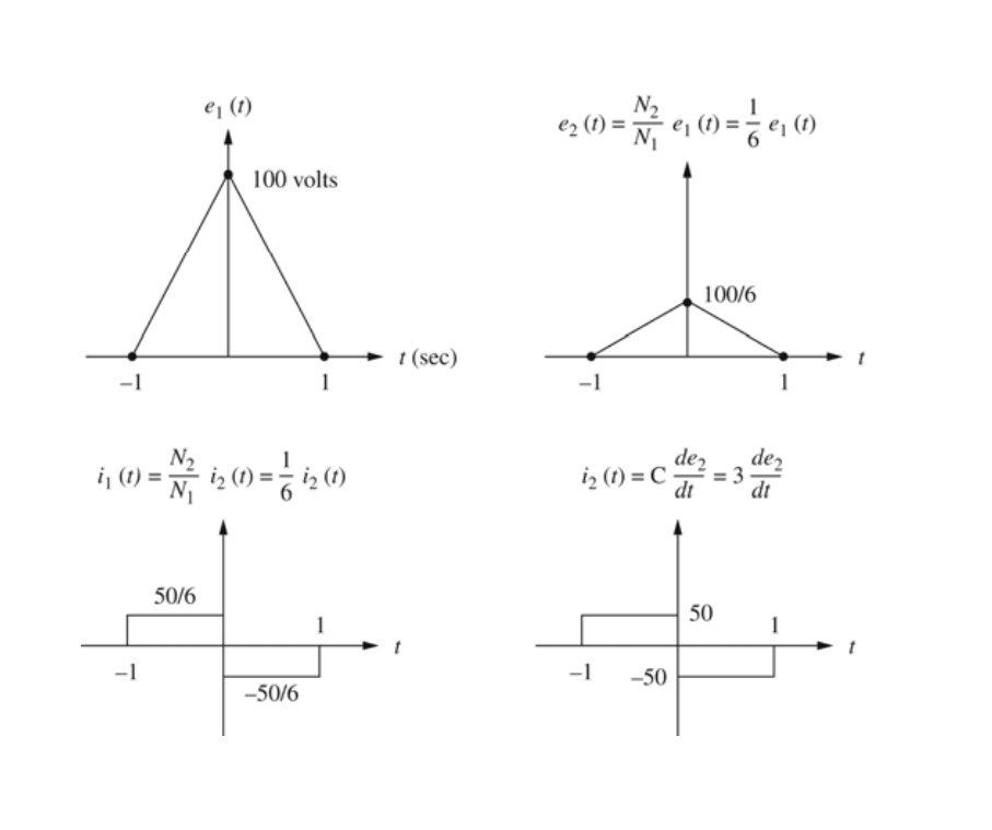
Consider an ideal transformer with and turns. Let winding 1 be connected to a source whose voltage is volts for and for second. A 3 -farad capacitor is connected across winding 2 . Sketch , and versus time .
2
A single-phase distribution transformer is used as a step-down transformer. The load, which is connected to the 240 -volt secondary winding, absorbs at 0.8 power factor lagging and is at 230 volts. Assuming an ideal transformer, calculate the following: (a) primary voltage, (b) load impedance, (c) load impedance referred to the primary, and (d) the real and reactive power supplied to the primary winding.
![(a) E_{1}=\frac{N_{1}}{N_{2}} E_{2}=\frac{2400}{240}(230)=2300 \mathrm{~V} (b) \bar{S}_{2}=\bar{E}_{2} \bar{I}_{2}^{*} ; \bar{I}_{2}=\left(\frac{\bar{S}_{2}}{\bar{E}_{2}}\right)^{*}=\left[\frac{80 \times 10^{3} \angle \cos ^{-1} 0.8}{230 \angle 0^{\circ}}\right]^{*}=347.8 \angle-36.87^{\circ} \begin{aligned} \bar{Ƶ}_{2}=\frac{\bar{E}_{2}}{\bar{I}_{2}}=\frac{230 \angle 0^{\circ}}{347.8 \angle-36.87^{\circ}} & =0.6613 \angle 36.87^{\circ} \Omega \\ & =0.529+j 0.397 \Omega \end{aligned} (c) \bar{Ƶ}_{1}^{\prime}=\left(\frac{N_{1}}{N_{2}}\right)^{2} \bar{Ƶ}_{2}=100 \bar{Ƶ}_{2}=66.13 \angle 36.87^{\circ} \Omega (d) P_{1}=P_{2}=80(0.8)=64 \mathrm{~kW} Q_{1}=Q_{2}=64 \tan \left(36.87^{\circ}\right)=48 \mathrm{kVAR}](https://storage.examlex.com/TB10648/11eec41d_0e3a_6e4f_ae1f_e7143df2f7d6_TB10648_00.jpg)
(a)
(b)
(c)
(d)
3
For a conceptual single-phase, phase-shifting transformer, the primary voltage leads the secondary voltage by . A load connected to the secondary winding absorbs at 0.9 power factor leading and at a voltage volts. Determine (a) the primary voltage, (b) primary and secondary currents, (c) load impedance referred to the primary winding, and (d) complex power supplied to the primary winding.
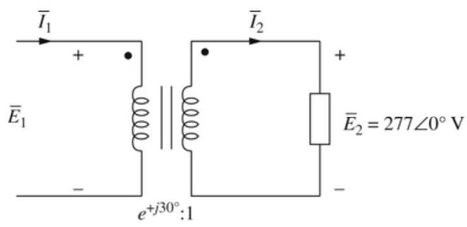
(a)
(b)
(c)
(d)
delivered to primary
4
The following data are obtained when open-circuit and short-circuit tests are performed on a single-phase, , distribution transformer.
(a) Neglecting the series impedance, determine the exciting admittance referred to the high-voltage side. (b) Neglecting the exciting admittance, determine the equivalent series impedance referred to the high-voltage side. (c) Assuming equal series impedances for the primary and referred secondary, obtain an equivalent T-circuit referred to the high-voltage side.
(a) Neglecting the series impedance, determine the exciting admittance referred to the high-voltage side. (b) Neglecting the exciting admittance, determine the equivalent series impedance referred to the high-voltage side. (c) Assuming equal series impedances for the primary and referred secondary, obtain an equivalent T-circuit referred to the high-voltage side.
Unlock Deck
Unlock for access to all 18 flashcards in this deck.
Unlock Deck
k this deck
5
A single-phase distribution transformer has a equivalent leakage reactance and a 6000 -ohm magnetizing reactance referred to the high-voltage side. If rated voltage is applied to the high-voltage winding, calculate the open-circuit secondary voltage. Neglect and losses. Assume equal series leakage reactances for the primary and referred secondary.
Unlock Deck
Unlock for access to all 18 flashcards in this deck.
Unlock Deck
k this deck
6
Using the transformer ratings as base quantities, work Test Bank Problem 3.5 in per unit.
Unlock Deck
Unlock for access to all 18 flashcards in this deck.
Unlock Deck
k this deck
7
A balanced Y-connected voltage source with volts is applied to a balanced- load in parallel with a balanced- load, where and ohms. The load is solidly grounded. Using base values of and volts, calculate the source current in per-unit and in amperes.
Unlock Deck
Unlock for access to all 18 flashcards in this deck.
Unlock Deck
k this deck
8
Consider a bank of three single-phase two-winding transformers whose high-voltage terminals are connected to a three-phase, feeder. The low-voltage terminals are connected to a three-phase substation load rated 2.4 MVA and . Determine the required voltage, current, and MVA ratings of both windings of each transformer, when the high-voltage/low-voltage windings are connected (a) , (b) , (c) , and (d) .
Unlock Deck
Unlock for access to all 18 flashcards in this deck.
Unlock Deck
k this deck
9
The leakage reactance of a three-phase, 500 -MVA, -kV transformer is 0.09 per unit based on its own ratings. The winding has a solidly grounded neutral. Draw the per-unit equivalent circuit. Neglect the exciting admittance and assume American standard phase shift.
Unlock Deck
Unlock for access to all 18 flashcards in this deck.
Unlock Deck
k this deck
10
Choosing system bases to be 360/24 kV and 100 MVA, redraw the per-unit equivalent circuit for Test Bank Problem 3.9
Unlock Deck
Unlock for access to all 18 flashcards in this deck.
Unlock Deck
k this deck
11
Consider the single-line diagram of the power system shown in Figure P3.11. Equipment rating are:}
Neglecting resistance, transformer phase shift, and magnetizing reactance, draw the equivalent reactance diagram. Use a base of and for the 40 -ohm line. Determine the per-unit reactances.
FIGURE P3.11
Neglecting resistance, transformer phase shift, and magnetizing reactance, draw the equivalent reactance diagram. Use a base of and for the 40 -ohm line. Determine the per-unit reactances.
FIGURE P3.11
Unlock Deck
Unlock for access to all 18 flashcards in this deck.
Unlock Deck
k this deck
12
For the power system in Test Bank Problem 3.11, the synchronous motor absorbs 1200 MW at 0.8 power factor leading with the bus 3 voltage at . Determine the bus 1 and bus 2 voltages in . Assume that generators 1 and 2 deliver equal real powers and equal reactive powers. Also assume a balanced three-phase system with positive-sequence sources.
Unlock Deck
Unlock for access to all 18 flashcards in this deck.
Unlock Deck
k this deck
13
Three single-phase transformers, each rated , with an equivalent series reactance of 0.12 per unit divided equally between primary and secondary, are connected in a three-phase bank. The high-voltage windings are Y connected and their terminals are directly connected to a three-phase bus. The secondary terminals are all shorted together. Find the currents entering the high-voltage terminals and leaving the low-voltage terminals if the low-voltage windings are (a) connected, (b) connected.
Unlock Deck
Unlock for access to all 18 flashcards in this deck.
Unlock Deck
k this deck
14
A 100-MVA, 13.2-kV three-phase generator, which has a positive-sequence reactance of 1.2 per unit on the generator base, is connected to a 110 -MVA, step-up transformer with a series impedance of per unit on its own base. (a) Calculate the per-unit generator reactance on the transformer base. (b) The load at the transformer terminals is at unity power factor and at . Choosing the transformer high-side voltage as the reference phasor, draw a phasor diagram for this condition. (c) For the condition of part (b), find the transformer low-side voltage and the generator internal voltage behind its reactance. Also compute the generator output power and power factor.
Unlock Deck
Unlock for access to all 18 flashcards in this deck.
Unlock Deck
k this deck
15
Figure P3.15 shows a one-line diagram of a system in which the three-phase generator is rated 300 MVA, with a subtransient reactance of 0.2 per unit and with its neutral grounded through a reactor. The transmission line is long with a series reactance of . The three-phase transformer is rated with a leakage reactance of 0.1 per unit. Transformer is composed of three single-phase transformers, each rated with a leakage reactance of 0.1 per unit. Two motors and with a subtransient reactance of 0.2 per unit for each motor represent the load. has a rated input of 200 MVA with its neutral grounded through a current-limiting reactor. has a rated input of 100 MVA with its neutral not connected to ground. Neglect phase shifts associated with the transformers. Choose the generator rating as base in the generator circuit and draw the positive-sequence reactance diagram showing all reactances in per unit.
Figure P3.15
Figure P3.15
Unlock Deck
Unlock for access to all 18 flashcards in this deck.
Unlock Deck
k this deck
16
A single-phase three-winding transformer has the following parameters: , and per unit. Three identical transformers, as described, are connected with their primaries in (solidly grounded neutral) and with their secondaries and tertiaries in . Draw the per-unit sequence networks of this transformer bank.
Unlock Deck
Unlock for access to all 18 flashcards in this deck.
Unlock Deck
k this deck
17
The ratings of a three-phase three-winding transformer are:
Primary (1): Y connected, MVA
Secondary (2): Y connected, MVA
Tertiary (3): connected, MVA
Neglecting winding resistances and exciting current, the per-unit leakage reactances are:
(a) Determine the per-unit reactances of the equivalent circuit on a 20-MVA, base at the primary terminals. (b) Purely resistive loads of at and at are connected to the secondary and tertiary sides of the transformer, respectively. Draw the per-unit impedance diagram, showing the per-unit impedances on a base at the primary terminals.
Unlock Deck
Unlock for access to all 18 flashcards in this deck.
Unlock Deck
k this deck
18
A single-phase -volt, two-winding distribution transformer is connected as an autotransformer to step up the voltage from 2400 to 2640 volts. (a) Draw a schematic diagram of this arrangement, showing all voltages and currents when delivering full load at rated voltage. (b) Find the permissible kVA rating of the autotransformer if the winding currents and voltages are not to exceed the rated values as a two-winding transformer. How much of this kVA rating is transformed by magnetic induction? (c) The following data are obtained from tests carried out on the transformer when it is connected as a two-winding transformer:
Open-circuit test with the low-voltage terminals excited:
Applied voltage , Input current , Input power .
Short-circuit test with the high-voltage terminals excited:
Applied voltage , Input current , Input power .
Based on the data, compute the efficiency of the autotransformer corresponding to full load, rated voltage, and 0.8 power factor lagging. Comment on why the efficiency is higher as an autotransformer than as a two-winding transformer.
Unlock Deck
Unlock for access to all 18 flashcards in this deck.
Unlock Deck
k this deck
Unlock Deck
Unlock for access to all 18 flashcards in this deck.


