Deck 22: Electromagnetic Induction
Full screen (f)
Question
Question
Question
The figure shows a uniform magnetic field that is normal to the plane of a conducting loop with resistance R. Which one of the following changes will cause an induced current to flow through the resistor? 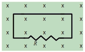
A)decreasing the area of the loop
B)decreasing the magnitude of the magnetic field
C)increasing the magnitude of the magnetic field
D)rotating the loop through 90° about an axis in the plane of the paper
E)all of the above
A)decreasing the area of the loop
B)decreasing the magnitude of the magnetic field
C)increasing the magnitude of the magnetic field
D)rotating the loop through 90° about an axis in the plane of the paper
E)all of the above
Question
Question
A long, straight wire is in the same plane as a rectangular, conducting loop. The wire carries a constant current I as shown in the figure. Which one of the following statements is true if the wire is suddenly moved toward the loop? 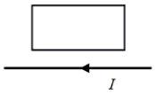
A)There will be no induced emf and no induced current.
B)There will be an induced emf, but no induced current.
C)There will be an induced current that is clockwise around the loop.
D)There will be an induced current that is counterclockwise around the loop.
E)There will be an induced electric field that is clockwise around the loop.
Question
The figure shows a uniform, 3.0-T magnetic field that is normal to the plane of a conducting, circular loop with a resistance of 1.5 and a radius of 0.024 m. The magnetic field is directed out of the paper as shown. Note: The area of the non-circular portion of the wire is considered negligible compared to that of the circular loop. 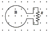
-If the magnetic field is held constant at 3.0 T and the loop is pulled out of the region that contains the field in 0.2 s, what is the magnitude of the average induced emf in the loop?
A)8.6 × 10⁻³ V
B)9.8 × 10⁻² V
C)2.7 × 10⁻² V
D)5.4 × 10⁻² V
E)6.4 × 10⁻² V
-If the magnetic field is held constant at 3.0 T and the loop is pulled out of the region that contains the field in 0.2 s, what is the magnitude of the average induced emf in the loop?
A)8.6 × 10⁻³ V
B)9.8 × 10⁻² V
C)2.7 × 10⁻² V
D)5.4 × 10⁻² V
E)6.4 × 10⁻² V
Question
A long, straight wire is in the same plane as a wooden, non-conducting loop. The wire carries an increasing current I in the direction shown in the figure. 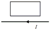
A)There will be no induced emf and no induced current.
B)There will be a counterclockwise induced emf, but no induced current.
C)There will be a clockwise induced emf, but no induced current.
D)There will be a clockwise induced current in the loop.
E)There will be a counterclockwise induced current in the loop.
Question
A 1.2-kg rod that has a length of 1.0 m and a resistance of 5.0 slides with constant speed down a pair of frictionless vertical conducting rails that are joined at the bottom. Other than the rod, the rest of the circuit is resistanceless. A uniform magnetic field of magnitude 3.0 T is perpendicular to the plane formed by the rod and the rails as shown. Determine the speed of the rod. 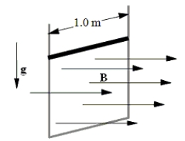
A)0.38 m/s
B)0.90 m/s
C)2.6 m/s
D)6.5 m/s
E)8.7 m/s
A)0.38 m/s
B)0.90 m/s
C)2.6 m/s
D)6.5 m/s
E)8.7 m/s
Question
Question
The figure shows a uniform, 3.0-T magnetic field that is normal to the plane of a conducting, circular loop with a resistance of 1.5 and a radius of 0.024 m. The magnetic field is directed out of the paper as shown. Note: The area of the non-circular portion of the wire is considered negligible compared to that of the circular loop.
-If the magnetic field is held constant at 3.0 T and the loop is pulled out of the region that contains the field in 0.2 s, at what rate is energy dissipated in R?
A)1.8 × 10⁻² W
B)3.6 × 10⁻² W
C)3.8 × 10⁻³ W
D)2.7 × 10⁻⁴ W
E)4.9 × 10⁻⁴ W
-If the magnetic field is held constant at 3.0 T and the loop is pulled out of the region that contains the field in 0.2 s, at what rate is energy dissipated in R?
A)1.8 × 10⁻² W
B)3.6 × 10⁻² W
C)3.8 × 10⁻³ W
D)2.7 × 10⁻⁴ W
E)4.9 × 10⁻⁴ W
Question
Question
Question
Question
A circular coil of wire has 25 turns and has a radius of 0.075 m. The coil is located in a variable magnetic field whose behavior is shown on the graph. At all times, the magnetic field is directed at an angle of 75° relative to the normal to the plane of a loop. What is the average emf induced in the coil in the time interval from t = 5.00 s to 7.50 s? 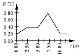
A)-18 mV
B)-49 mV
C)-92 mV
D)-140 mV
E)-180 mV
A)-18 mV
B)-49 mV
C)-92 mV
D)-140 mV
E)-180 mV
Question
Question
Question
The figure shows a uniform, 3.0-T magnetic field that is normal to the plane of a conducting, circular loop with a resistance of 1.5 and a radius of 0.024 m. The magnetic field is directed out of the paper as shown. Note: The area of the non-circular portion of the wire is considered negligible compared to that of the circular loop.
-What is the average current around the loop if the magnitude of the magnetic field is doubled in 0.4 s?
A)2.8 × 10⁻³ A, clockwise
B)4.5 × 10⁻³ A, clockwise
C)4.5 × 10⁻³ A, counterclockwise
D)9.0 × 10⁻³ A, clockwise
E)9.0 × 10⁻³ A, counterclockwise
-What is the average current around the loop if the magnitude of the magnetic field is doubled in 0.4 s?
A)2.8 × 10⁻³ A, clockwise
B)4.5 × 10⁻³ A, clockwise
C)4.5 × 10⁻³ A, counterclockwise
D)9.0 × 10⁻³ A, clockwise
E)9.0 × 10⁻³ A, counterclockwise
Question
The figure shows a uniform, 3.0-T magnetic field that is normal to the plane of a conducting, circular loop with a resistance of 1.5 and a radius of 0.024 m. The magnetic field is directed out of the paper as shown. Note: The area of the non-circular portion of the wire is considered negligible compared to that of the circular loop.
-What is the magnitude of the average induced emf in the loop if the magnitude of the magnetic field is doubled in 0.4 s?
A)0.43 V
B)0.65 V
C)0.014 V
D)0.027 V
E)0.038 V
-What is the magnitude of the average induced emf in the loop if the magnitude of the magnetic field is doubled in 0.4 s?
A)0.43 V
B)0.65 V
C)0.014 V
D)0.027 V
E)0.038 V
Question
A conducting bar moves to the left at a constant speed v on two conducting rails joined at the left as shown. As a result of the bar moving through a constant magnetic field, a current I is induced in the indicated direction. Which one of the following directions is that of the magnetic field? 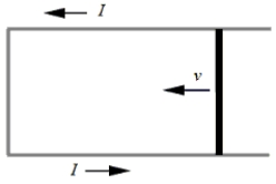
A)toward the right
B)toward the left
C)parallel to the long axis of the bar
D)into the page
E)out of the page
A)toward the right
B)toward the left
C)parallel to the long axis of the bar
D)into the page
E)out of the page
Question
Question
Question
A single conducting loop with an area of 2.0 m2 rotates in a uniform magnetic field so that the induced emf has a sinusoidal time dependence as shown. 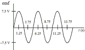
With what angular frequency does the loop rotate?
A)0.16 rad/s
B)0.30 rad/s
C)0.52 rad/s
D)0.80 rad/s
E)1.26 rad/s
With what angular frequency does the loop rotate?
A)0.16 rad/s
B)0.30 rad/s
C)0.52 rad/s
D)0.80 rad/s
E)1.26 rad/s
Question
Question
Two coils share a common axis as shown in the figure. The mutual inductance of this pair of coils is 6.0 mH. If the current in coil 1 is changing at the rate of 3.5 A/s, what is the magnitude of the emf generated in coil 2? 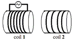
A)5.8 × 10⁻⁴ V
B)1.7 × 10⁻³ V
C)3.5 × 10⁻³ V
D)1.5 × 10⁻² V
E)2.1 × 10⁻² V
A)5.8 × 10⁻⁴ V
B)1.7 × 10⁻³ V
C)3.5 × 10⁻³ V
D)1.5 × 10⁻² V
E)2.1 × 10⁻² V
Question
Two conducting loops carry equal currents I in the same direction as shown in the figure. If the current in the upper loop suddenly drops to zero, what will happen to the current in the lower loop according to Lenz's law? 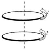
A)The current in the lower loop will decrease.
B)The current in the lower loop will increase.
C)The current in the lower loop will not change.
D)The current in the lower loop will also drop to zero.
E)The current in the lower loop will reverse its direction.
A)The current in the lower loop will decrease.
B)The current in the lower loop will increase.
C)The current in the lower loop will not change.
D)The current in the lower loop will also drop to zero.
E)The current in the lower loop will reverse its direction.
Question
A metal ring is dropped from rest below a bar magnet that is fixed in position as suggested in the figure. An observer views the ring from below. Which one of the following statements concerning this situation is true? 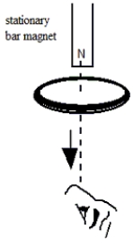
A)As the ring falls, an induced current will flow counterclockwise as viewed by the observer.
B)As the ring falls, an induced current will flow clockwise as viewed by the observer.
C)As the ring falls, there will be an induced magnetic field around the ring that appears counterclockwise as viewed by the observer.
D)As the ring falls, there will be an induced magnetic field around the ring that appears clockwise as viewed by the observer.
E)Since the magnet is stationary, there will be no induced current in the ring.
Question
A 0.100-m long solenoid has a radius of 0.050 m and 1.50 × 10⁴ turns. The current in the solenoid changes at a rate of 6.0 A/s. A conducting loop of radius 0.0200 m is placed at the center of the solenoid with its axis the same as that of the solenoid as shown. 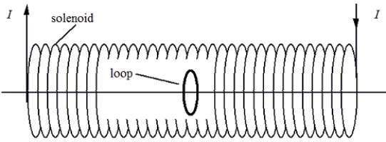
Determine the mutual inductance of this combination.
A)1.8 × 10⁻⁴ H
B)2.4 × 10⁻⁴ H
C)3.6 × 10⁻⁴ H
D)4.4 × 10⁻⁴ H
E)5.9 × 10⁻⁴ H
Determine the mutual inductance of this combination.
A)1.8 × 10⁻⁴ H
B)2.4 × 10⁻⁴ H
C)3.6 × 10⁻⁴ H
D)4.4 × 10⁻⁴ H
E)5.9 × 10⁻⁴ H
Question
Question
A circuit is pulled with a 21-N force toward the right to maintain a constant speed v. At the instant shown, the loop is partially in and partially out of a uniform magnetic field that is directed into the paper. As the circuit moves, a 4.0-A current flows through a 6.0- resistor. 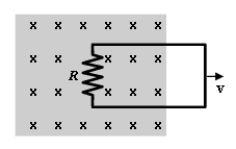
-What is the magnitude of v?
A)1.5 m/s
B)4.6 m/s
C)6.4 m/s
D)7.8 m/s
E)9.0 m/s
-What is the magnitude of v?
A)1.5 m/s
B)4.6 m/s
C)6.4 m/s
D)7.8 m/s
E)9.0 m/s
Question
A sheet of copper is pulled at constant velocity v from a region that contains a uniform magnetic field. At the instant shown in the figure, the sheet is partially in and partially out of the field. The induced emf in the sheet leads to the eddy current shown. Which one of the following statements concerning the direction of the magnetic field is true? 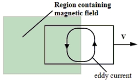
A)The magnetic field points to the right.
B)The magnetic field points to the left.
C)The magnetic field points into the paper.
D)The magnetic field points out of the paper.
E)The direction of the magnetic field cannot be determined from the information given.
A)The magnetic field points to the right.
B)The magnetic field points to the left.
C)The magnetic field points into the paper.
D)The magnetic field points out of the paper.
E)The direction of the magnetic field cannot be determined from the information given.
Question
A circular coil has 275 turns and a radius of 0.045 m. The coil is used as an ac generator by rotating it in a 0.500 T magnetic field, as shown in the figure. At what angular speed should the coil be rotated so that the maximum emf is 175 V? 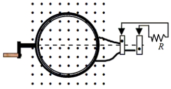
A)28 rad/s
B)50 rad/s
C)130 rad/s
D)200 rad/s
E)490 rad/s
A)28 rad/s
B)50 rad/s
C)130 rad/s
D)200 rad/s
E)490 rad/s
Question
A single conducting loop with an area of 2.0 m2 rotates in a uniform magnetic field so that the induced emf has a sinusoidal time dependence as shown.
Determine the strength of the magnetic field in which the loop rotates.
A)0.5 T
B)2.4 T
C)3.0 T
D)7.5 T
E)18.8 T
Determine the strength of the magnetic field in which the loop rotates.
A)0.5 T
B)2.4 T
C)3.0 T
D)7.5 T
E)18.8 T
Question
A circuit is pulled with a 21-N force toward the right to maintain a constant speed v. At the instant shown, the loop is partially in and partially out of a uniform magnetic field that is directed into the paper. As the circuit moves, a 4.0-A current flows through a 6.0- resistor.
-Which one of the following statements concerning this situation is true?
A)The temperature of the circuit remains constant.
B)The induced current flows clockwise around the circuit.
C)Since the circuit moves with constant speed, the force F does zero work.
D)If the circuit were replaced with a wooden loop, there would be no induced emf.
E)As the circuit moves through the field, the field does work to produce the current.
Question
A single conducting loop with an area of 2.0 m2 rotates in a uniform magnetic field so that the induced emf has a sinusoidal time dependence as shown.
What is the period of the induced current?
A)1.25 s
B)2.50 s
C)3.75 s
D)5.00 s
E)6.25 s
What is the period of the induced current?
A)1.25 s
B)2.50 s
C)3.75 s
D)5.00 s
E)6.25 s
Question
Question
Question
Question
The figure shows a circular, conducting loop that is connected to a 5.0-V battery and a switch S. Immediately after the switch S is closed, the current through the loop changes at a rate of 15 A/s and the emf induced in the loop has a magnitude of 5.0 V. Determine the self-inductance of the coil. 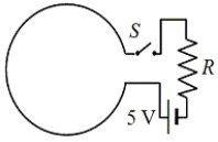
A)0.33 H
B)0.60 H
C)1.5 H
D)3.0 H
E)5.0 H
A)0.33 H
B)0.60 H
C)1.5 H
D)3.0 H
E)5.0 H
Question
A 0.100-m long solenoid has a radius of 0.050 m and 1.50 × 10⁴ turns. The current in the solenoid changes at a rate of 6.0 A/s. A conducting loop of radius 0.0200 m is placed at the center of the solenoid with its axis the same as that of the solenoid as shown.
What is the magnetic flux through the small loop when the current through the solenoid is 2.50 A?
A)2.95 × 10⁻² Wb
B)7.28 × 10⁻² Wb
C)2.95 × 10⁻⁴ Wb
D)4.38 × 10⁻⁴ Wb
E)5.92 × 10⁻⁴ Wb
What is the magnetic flux through the small loop when the current through the solenoid is 2.50 A?
A)2.95 × 10⁻² Wb
B)7.28 × 10⁻² Wb
C)2.95 × 10⁻⁴ Wb
D)4.38 × 10⁻⁴ Wb
E)5.92 × 10⁻⁴ Wb
Question
Question
The figure shows a uniform magnetic field that is normal to the plane of the conducting loop of resistance R. Note: the area of the non-circular portion of the circuit is negligible compared to that of the loop. 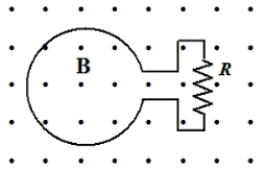
Which entry in the table below correctly pairs the change in the system with the direction of the induced current through R?
A)
B)
C)
D)
E)
Which entry in the table below correctly pairs the change in the system with the direction of the induced current through R?
A)
B)
C)
D)
E)
Question
Question
Question
Question
Two coils, 1 and 2, with iron cores are positioned as shown in the figure. Coil 1 is part of a circuit with a battery and a switch. 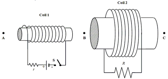
Assume that S has been closed for a long time. Which one of the following statements is true if S is suddenly opened?
A)There is no induced current through R.
B)There is no induced magnetic field in coil 2.
C)There is an induced current in R that flows from right to left.
D)There is an induced magnetic field in coil 2 that points toward C.
E)There is an induced magnetic field in coil 2 that points toward B.
Question
The figure shows a uniform magnetic field that is normal to the plane of the conducting loop of resistance R. Note: the area of the non-circular portion of the circuit is negligible compared to that of the loop.
A circular loop of copper wire with an area of 2.0 m2 lies in a plane perpendicular to a time-dependent magnetic field oriented as shown. The time-dependence of the field is shown in the graph.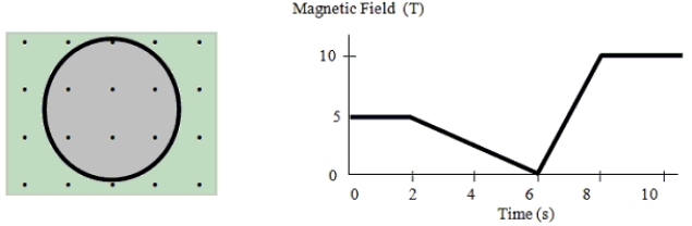 Which one of the entries in the table below is incorrect?
A)
B)
C)
D)
E)
A circular loop of copper wire with an area of 2.0 m2 lies in a plane perpendicular to a time-dependent magnetic field oriented as shown. The time-dependence of the field is shown in the graph.
Which one of the entries in the table below is incorrect? A)
B)
C)
D)
E)
Question
A 0.100-m long solenoid has a radius of 0.050 m and 1.50 × 10⁴ turns. The current in the solenoid changes at a rate of 6.0 A/s. A conducting loop of radius 0.0200 m is placed at the center of the solenoid with its axis the same as that of the solenoid as shown.
Determine the induced emf in the loop.
A)0.7 × 10⁻³ V
B)1.4 × 10⁻³ V
C)2.8 × 10⁻³ V
D)5.6 × 10⁻³ V
E)zero volts
Determine the induced emf in the loop.
A)0.7 × 10⁻³ V
B)1.4 × 10⁻³ V
C)2.8 × 10⁻³ V
D)5.6 × 10⁻³ V
E)zero volts
Question
Question
Two coils, 1 and 2, with iron cores are positioned as shown in the figure. Coil 1 is part of a circuit with a battery and a switch.
Assume that S has been closed for a long time. Which one of the following changes will not result in an induced current in coil 2 that flows from left to right through R.
A)Coil 1 and its core are moved toward A.
B)Coil 2 and its core are moved toward B.
C)Coil 2 and its core are moved toward C.
D)The switch S is opened.
E)The iron core is removed from coil 1.
Question
The figure shows a uniform magnetic field that is normal to the plane of the conducting loop of resistance R. Note: the area of the non-circular portion of the circuit is negligible compared to that of the loop.
-Suppose that the radius of the loop is 0.500 m. At what rate must B change with time if the emf induced in the loop is volts?
A)12.0 T/s
B)18.8 T/s
C)24.0 T/s
D)37.7 T/s
E)49.2 T/s
-Suppose that the radius of the loop is 0.500 m. At what rate must B change with time if the emf induced in the loop is volts?
A)12.0 T/s
B)18.8 T/s
C)24.0 T/s
D)37.7 T/s
E)49.2 T/s
Question
A 0.100-m long solenoid has a radius of 0.050 m and 1.50 × 10⁴ turns. The current in the solenoid changes at a rate of 6.0 A/s. A conducting loop of radius 0.0200 m is placed at the center of the solenoid with its axis the same as that of the solenoid as shown.
Determine the induced emf in the loop if the loop is oriented so that its axis is perpendicular to the axis of the solenoid, instead of parallel.
A)0.7 × 10⁻⁴ V
B)1.4 × 10⁻⁴ V
C)2.8 × 10⁻⁴ V
D)5.6 × 10⁻⁴ V
E)zero volts
Determine the induced emf in the loop if the loop is oriented so that its axis is perpendicular to the axis of the solenoid, instead of parallel.
A)0.7 × 10⁻⁴ V
B)1.4 × 10⁻⁴ V
C)2.8 × 10⁻⁴ V
D)5.6 × 10⁻⁴ V
E)zero volts
Question
Question
Question
Two coils, 1 and 2, with iron cores are positioned as shown in the figure. Coil 1 is part of a circuit with a battery and a switch.
Assume S has been closed for a long time. Which one of the following statements is true when coil 1 and its core are moved toward point B?
A)There is no induced current in r.
B)There is a magnetic field in coil 1 that points toward B.
C)There is an induced current in R that flows from left to right.
D)There is an induced current in R that flows from right to left.
E)There is an induced magnetic field in coil 2 that points toward B.
Question
Two coils, 1 and 2, with iron cores are positioned as shown in the figure. Coil 1 is part of a circuit with a battery and a switch.
Assume the switch S has been closed for a long time. Which one of the following statements is true?
A)An induced current will flow from right to left in R.
B)An induced current will flow from left to right in r.
C)A magnetic field that points toward B appears inside coil 1.
D)An induced magnetic field that points toward B appears inside coil 2.
E)A current will pass through r, but there will be no current through R.
Question
Two coils, 1 and 2, with iron cores are positioned as shown in the figure. Coil 1 is part of a circuit with a battery and a switch.
Assume that S has been closed for a long time. Which one of the following changes will result in an induced magnetic field in coil 2 that points toward C?
A)The switch S is opened.
B)The iron core is removed from coil 1.
C)Coil 1 and its core are moved toward A.
D)Coil 1 and its core are moved toward B.
E)Coil 2 and its core are moved toward C.
Question
A 0.100-m long solenoid has a radius of 0.050 m and 1.50 × 10⁴ turns. The current in the solenoid changes at a rate of 6.0 A/s. A conducting loop of radius 0.0200 m is placed at the center of the solenoid with its axis the same as that of the solenoid as shown.
Determine the self-induced emf in the solenoid due to the changing current.
A)60 V
B)98 V
C)130 V
D)180 V
E)250 V
Determine the self-induced emf in the solenoid due to the changing current.
A)60 V
B)98 V
C)130 V
D)180 V
E)250 V
Question
Two coils, 1 and 2, with iron cores are positioned as shown in the figure. Coil 1 is part of a circuit with a battery and a switch.
Assume that S has been closed for a long time. Which one of the following statements is true if coil 2 is moved toward C?
A)There is an induced magnetic field in coil 2 that points toward B.
B)There is an induced magnetic field in coil 2 that points toward C.
C)There is an induced current in R that flows from right to left.
D)There is an induced north pole at the right end of coil 2.
E)There is no induced current in R.
Question
Two coils, 1 and 2, with iron cores are positioned as shown in the figure. Coil 1 is part of a circuit with a battery and a switch.
Immediately after the switch S is closed, which one of the following statements is true?
A)An induced current will flow from right to left in R.
B)An induced current will flow from left to right in r.
C)A magnetic field that points toward B appears inside coil 1.
D)An induced magnetic field that points toward B appears inside coil 2.
E)A current will pass through r, but there will be no current through R.
Question
In the drawing, a coil of wire is wrapped around a cylinder from which an iron core extends upward. The ends of the coil are connected to an ac voltage source. After the alternating current is established in the coil, an aluminum ring of resistance R is placed onto the iron core and released. Which one of the following statements concerning this situation is false? 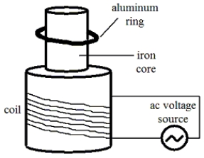
A)The induced current in the ring is an alternating current.
B)The temperature of the ring will increase.
C)At any instant, the direction of the induced current in the ring is in the same direction as that in the coil.
D)The induced magnetic field in the ring may by directed either upward or downward at an instant when the direction of the magnetic field generated by the current in the coil is upward.
E)The ring may remain suspended at the position shown with no vertical movement of its center of mass.
Question
A loop with a resistance of 4.0 is pushed to the left at a constant speed of 2.0 m/s by a 24 N force. At the instant shown in the figure, the loop is partially in and partially out of a uniform magnetic field. An induced current flows from left to right through the resistor. The length and width of the loop are 2.0 m and 1.0 m, respectively. 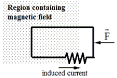
-Determine the magnitude of the induced current through the resistor.
A)2.0 A
B)3.5 A
C)4.6 A
D)7.2 A
E)11 A
-Determine the magnitude of the induced current through the resistor.
A)2.0 A
B)3.5 A
C)4.6 A
D)7.2 A
E)11 A
Question
A loop is pulled with a force F to the right to maintain a constant speed of 8.0 m/s. The loop has a length of 0.15 m, a width of 0.080 m, and a resistance of 200.0 . At the instant shown, the loop is partially in and partially out of a uniform magnetic field that is directed into the paper. The magnitude of the field is 1.2 T. 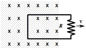
-What is the induced current in the loop?
A)0.048 A
B)0.024 A
C)7.2 × 10⁻³ A
D)3.8 × 10⁻³ A
E)zero amperes
-What is the induced current in the loop?
A)0.048 A
B)0.024 A
C)7.2 × 10⁻³ A
D)3.8 × 10⁻³ A
E)zero amperes
Question
A loop is pulled with a force F to the right to maintain a constant speed of 8.0 m/s. The loop has a length of 0.15 m, a width of 0.080 m, and a resistance of 200.0 . At the instant shown, the loop is partially in and partially out of a uniform magnetic field that is directed into the paper. The magnitude of the field is 1.2 T.
-Determine the magnitude of the force required to pull the loop.
A)1.3 × 10⁻⁴ N
B)2.1 × 10⁻⁴ N
C)3.7 × 10⁻⁴ N
D)6.8 × 10⁻⁴ N
E)9.0 × 10⁻⁴ N
-Determine the magnitude of the force required to pull the loop.
A)1.3 × 10⁻⁴ N
B)2.1 × 10⁻⁴ N
C)3.7 × 10⁻⁴ N
D)6.8 × 10⁻⁴ N
E)9.0 × 10⁻⁴ N
Question
A flexible, circular conducting loop of radius 0.15 m and resistance 4.0 lies in a uniform magnetic field of 0.25 T. The loop is pulled on opposite sides by equal forces and stretched until its enclosed area is essentially zero m2, as suggested in the drawings. It takes 0.30 s to close the loop. 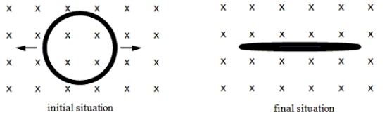
-Which one of the following phrases best describes the direction of the induced magnetic field generated by the current induced in the loop while the loop is being stretched?
A)clockwise
B)counterclockwise
C)into the page
D)out of the page
E)The induced field is zero.
-Which one of the following phrases best describes the direction of the induced magnetic field generated by the current induced in the loop while the loop is being stretched?
A)clockwise
B)counterclockwise
C)into the page
D)out of the page
E)The induced field is zero.
Question
A loop with a resistance of 4.0 is pushed to the left at a constant speed of 2.0 m/s by a 24 N force. At the instant shown in the figure, the loop is partially in and partially out of a uniform magnetic field. An induced current flows from left to right through the resistor. The length and width of the loop are 2.0 m and 1.0 m, respectively.
-Determine the magnitude of the uniform magnetic field.
A)2.2 T
B)3.5 T
C)6.4 T
D)7.0 T
E)9.1 T
-Determine the magnitude of the uniform magnetic field.
A)2.2 T
B)3.5 T
C)6.4 T
D)7.0 T
E)9.1 T
Question
A flexible, circular conducting loop of radius 0.15 m and resistance 4.0 lies in a uniform magnetic field of 0.25 T. The loop is pulled on opposite sides by equal forces and stretched until its enclosed area is essentially zero m2, as suggested in the drawings. It takes 0.30 s to close the loop.
-At what rate is heat generated in the loop?
A)3.6 × 10⁻³ W
B)8.7 × 10⁻⁴ W
C)8.7 × 10⁴ W
D)8.1 × 10⁵ W
E)8.1 × 10⁻⁵ W
-At what rate is heat generated in the loop?
A)3.6 × 10⁻³ W
B)8.7 × 10⁻⁴ W
C)8.7 × 10⁴ W
D)8.1 × 10⁵ W
E)8.1 × 10⁻⁵ W
Question
A loop with a resistance of 4.0 is pushed to the left at a constant speed of 2.0 m/s by a 24 N force. At the instant shown in the figure, the loop is partially in and partially out of a uniform magnetic field. An induced current flows from left to right through the resistor. The length and width of the loop are 2.0 m and 1.0 m, respectively.
-At what rate is energy dissipated by the resistor?
A)130 W
B)96 W
C)32 W
D)49 W
E)8.0 W
-At what rate is energy dissipated by the resistor?
A)130 W
B)96 W
C)32 W
D)49 W
E)8.0 W
Question
A loop with a resistance of 4.0 is pushed to the left at a constant speed of 2.0 m/s by a 24 N force. At the instant shown in the figure, the loop is partially in and partially out of a uniform magnetic field. An induced current flows from left to right through the resistor. The length and width of the loop are 2.0 m and 1.0 m, respectively.
-Determine the magnitude of the induced emf in the loop.
A)2.0 V
B)4.0 V
C)8.0 V
D)14 V
E)16 V
-Determine the magnitude of the induced emf in the loop.
A)2.0 V
B)4.0 V
C)8.0 V
D)14 V
E)16 V
Question
A loop is pulled with a force F to the right to maintain a constant speed of 8.0 m/s. The loop has a length of 0.15 m, a width of 0.080 m, and a resistance of 200.0 . At the instant shown, the loop is partially in and partially out of a uniform magnetic field that is directed into the paper. The magnitude of the field is 1.2 T.
-What is the magnitude of the emf induced in the loop?
A)zero volts
B)0.77 V
C)1.4 V
D)4.9 V
E)9.6 V
-What is the magnitude of the emf induced in the loop?
A)zero volts
B)0.77 V
C)1.4 V
D)4.9 V
E)9.6 V
Question
A loop with a resistance of 4.0 is pushed to the left at a constant speed of 2.0 m/s by a 24 N force. At the instant shown in the figure, the loop is partially in and partially out of a uniform magnetic field. An induced current flows from left to right through the resistor. The length and width of the loop are 2.0 m and 1.0 m, respectively.
-What is the direction of the magnetic field?
A)to the left
B)to the right
C)out of the paper
D)into the paper
E)toward the top of the page
-What is the direction of the magnetic field?
A)to the left
B)to the right
C)out of the paper
D)into the paper
E)toward the top of the page
Question
A flexible, circular conducting loop of radius 0.15 m and resistance 4.0 lies in a uniform magnetic field of 0.25 T. The loop is pulled on opposite sides by equal forces and stretched until its enclosed area is essentially zero m2, as suggested in the drawings. It takes 0.30 s to close the loop.
-Determine the magnitude of the emf induced in the loop.
A)1.2 × 10⁻¹ V
B)1.8 × 10⁻² V
C)1.8 × 10² V
D)5.9 × 10⁻² V
E)5.9 × 10² V
-Determine the magnitude of the emf induced in the loop.
A)1.2 × 10⁻¹ V
B)1.8 × 10⁻² V
C)1.8 × 10² V
D)5.9 × 10⁻² V
E)5.9 × 10² V

Unlock Deck
Sign up to unlock the cards in this deck!
Unlock Deck
Unlock Deck
1/71
Play
Full screen (f)
Deck 22: Electromagnetic Induction
1
A 0.60-T magnetic field is directed perpendicular to the plane of a circular loop of radius 0.40 m. What is the magnitude of the magnetic flux through the loop?
A)0.049 Wb
B)0.098 Wb
C)0.24 Wb
D)0.30 Wb
E)zero Wb
A)0.049 Wb
B)0.098 Wb
C)0.24 Wb
D)0.30 Wb
E)zero Wb
0.30 Wb
2
A conducting loop of wire is placed in a magnetic field that is normal to the plane of the loop. Which one of the following actions will not result in an induced current in the loop?
A)Rotate the loop about an axis that is parallel to the field and passes through the center of the loop.
B)Increase the strength of the magnetic field.
C)Decrease the area of the loop.
D)Decrease the strength of the magnetic field.
E)Rotate the loop about an axis that is perpendicular to the field and passes through the center of the loop.
Rotate the loop about an axis that is parallel to the field and passes through the center of the loop.
3
The figure shows a uniform magnetic field that is normal to the plane of a conducting loop with resistance R. Which one of the following changes will cause an induced current to flow through the resistor?
A)decreasing the area of the loop
B)decreasing the magnitude of the magnetic field
C)increasing the magnitude of the magnetic field
D)rotating the loop through 90° about an axis in the plane of the paper
E)all of the above
A)decreasing the area of the loop
B)decreasing the magnitude of the magnetic field
C)increasing the magnitude of the magnetic field
D)rotating the loop through 90° about an axis in the plane of the paper
E)all of the above
all of the above
4
A magnetic field is directed perpendicular to the plane of a 0.15-m × 0.30-m rectangular coil consisting of 240 loops of wire. To induce an average emf of -2.5 V in the coil, the magnetic field is increased from 0.1 T to 1.8 T during a time interval t. Determine t.
A)0.053 s
B)0.13 s
C)12 s
D)6.4 s
E)7.3 s
A)0.053 s
B)0.13 s
C)12 s
D)6.4 s
E)7.3 s
Unlock Deck
Unlock for access to all 71 flashcards in this deck.
Unlock Deck
k this deck
5
A long, straight wire is in the same plane as a rectangular, conducting loop. The wire carries a constant current I as shown in the figure. Which one of the following statements is true if the wire is suddenly moved toward the loop?
A)There will be no induced emf and no induced current.
B)There will be an induced emf, but no induced current.
C)There will be an induced current that is clockwise around the loop.
D)There will be an induced current that is counterclockwise around the loop.
E)There will be an induced electric field that is clockwise around the loop.
Unlock Deck
Unlock for access to all 71 flashcards in this deck.
Unlock Deck
k this deck
6
The figure shows a uniform, 3.0-T magnetic field that is normal to the plane of a conducting, circular loop with a resistance of 1.5 and a radius of 0.024 m. The magnetic field is directed out of the paper as shown. Note: The area of the non-circular portion of the wire is considered negligible compared to that of the circular loop.
-If the magnetic field is held constant at 3.0 T and the loop is pulled out of the region that contains the field in 0.2 s, what is the magnitude of the average induced emf in the loop?
A)8.6 × 10⁻³ V
B)9.8 × 10⁻² V
C)2.7 × 10⁻² V
D)5.4 × 10⁻² V
E)6.4 × 10⁻² V
-If the magnetic field is held constant at 3.0 T and the loop is pulled out of the region that contains the field in 0.2 s, what is the magnitude of the average induced emf in the loop?
A)8.6 × 10⁻³ V
B)9.8 × 10⁻² V
C)2.7 × 10⁻² V
D)5.4 × 10⁻² V
E)6.4 × 10⁻² V
Unlock Deck
Unlock for access to all 71 flashcards in this deck.
Unlock Deck
k this deck
7
A long, straight wire is in the same plane as a wooden, non-conducting loop. The wire carries an increasing current I in the direction shown in the figure.
A)There will be no induced emf and no induced current.
B)There will be a counterclockwise induced emf, but no induced current.
C)There will be a clockwise induced emf, but no induced current.
D)There will be a clockwise induced current in the loop.
E)There will be a counterclockwise induced current in the loop.
Unlock Deck
Unlock for access to all 71 flashcards in this deck.
Unlock Deck
k this deck
8
A 1.2-kg rod that has a length of 1.0 m and a resistance of 5.0 slides with constant speed down a pair of frictionless vertical conducting rails that are joined at the bottom. Other than the rod, the rest of the circuit is resistanceless. A uniform magnetic field of magnitude 3.0 T is perpendicular to the plane formed by the rod and the rails as shown. Determine the speed of the rod.
A)0.38 m/s
B)0.90 m/s
C)2.6 m/s
D)6.5 m/s
E)8.7 m/s
A)0.38 m/s
B)0.90 m/s
C)2.6 m/s
D)6.5 m/s
E)8.7 m/s
Unlock Deck
Unlock for access to all 71 flashcards in this deck.
Unlock Deck
k this deck
9
A conducting loop has an area of 0.065 m2 and is positioned such that a uniform magnetic field is perpendicular to the plane of the loop. When the magnitude of the magnetic field decreases to 0.30 T in 0.087 s, the average induced emf in the loop is 1.2 V. What is the initial value of the magnetic field?
A)0.42 T
B)0.75 T
C)0.87 T
D)1.2 T
E)1.9 T
A)0.42 T
B)0.75 T
C)0.87 T
D)1.2 T
E)1.9 T
Unlock Deck
Unlock for access to all 71 flashcards in this deck.
Unlock Deck
k this deck
10
The figure shows a uniform, 3.0-T magnetic field that is normal to the plane of a conducting, circular loop with a resistance of 1.5 and a radius of 0.024 m. The magnetic field is directed out of the paper as shown. Note: The area of the non-circular portion of the wire is considered negligible compared to that of the circular loop.
-If the magnetic field is held constant at 3.0 T and the loop is pulled out of the region that contains the field in 0.2 s, at what rate is energy dissipated in R?
A)1.8 × 10⁻² W
B)3.6 × 10⁻² W
C)3.8 × 10⁻³ W
D)2.7 × 10⁻⁴ W
E)4.9 × 10⁻⁴ W
-If the magnetic field is held constant at 3.0 T and the loop is pulled out of the region that contains the field in 0.2 s, at what rate is energy dissipated in R?
A)1.8 × 10⁻² W
B)3.6 × 10⁻² W
C)3.8 × 10⁻³ W
D)2.7 × 10⁻⁴ W
E)4.9 × 10⁻⁴ W
Unlock Deck
Unlock for access to all 71 flashcards in this deck.
Unlock Deck
k this deck
11
Which of the following units are equivalent to those of motional emf?
A)T . m/s
B)V . m2/s
C)J/s
D)A .
E)T . m
A)T . m/s
B)V . m2/s
C)J/s
D)A .
E)T . m
Unlock Deck
Unlock for access to all 71 flashcards in this deck.
Unlock Deck
k this deck
12
A uniform magnetic field passes through two areas, A1 and A2. The angles between the magnetic field and the normals of areas A1 and A2 are 30.0° and 60.0°, respectively. If the magnetic flux through the two areas is the same, what is the ratio A1/A2?
A)0.354
B)0.866
C)1.00
D)1.23
E)1.73
A)0.354
B)0.866
C)1.00
D)1.23
E)1.73
Unlock Deck
Unlock for access to all 71 flashcards in this deck.
Unlock Deck
k this deck
13
A 0.45-m metal rod moves 0.11 m in a direction that is perpendicular to a 0.80-T magnetic field in an elapsed time of 0.036 s. Assuming that the acceleration of the rod is zero m/s2, determine the emf that exists between the ends of the rod.
A)1.1 V
B)0.27 V
C)0.076 V
D)9.1 × 10⁻⁵ V
E)This cannot be determined without knowing the orientation of the rod relative to the magnetic field.
A)1.1 V
B)0.27 V
C)0.076 V
D)9.1 × 10⁻⁵ V
E)This cannot be determined without knowing the orientation of the rod relative to the magnetic field.
Unlock Deck
Unlock for access to all 71 flashcards in this deck.
Unlock Deck
k this deck
14
A circular coil of wire has 25 turns and has a radius of 0.075 m. The coil is located in a variable magnetic field whose behavior is shown on the graph. At all times, the magnetic field is directed at an angle of 75° relative to the normal to the plane of a loop. What is the average emf induced in the coil in the time interval from t = 5.00 s to 7.50 s?
A)-18 mV
B)-49 mV
C)-92 mV
D)-140 mV
E)-180 mV
A)-18 mV
B)-49 mV
C)-92 mV
D)-140 mV
E)-180 mV
Unlock Deck
Unlock for access to all 71 flashcards in this deck.
Unlock Deck
k this deck
15
A 250-turn solenoid carries a current of 9.0 A. The radius of the solenoid is 0.075 m; and its length is 0.14 m. Determine the magnetic flux through the circular cross-sectional area at the center of the solenoid.
A)1.8 × 10⁻⁵ Wb
B)9.9 × 10⁻⁵ Wb
C)3.6 × 10⁻⁴ Wb
D)7.0 × 10⁻⁴ Wb
E)2.2 × 10⁻³ Wb
A)1.8 × 10⁻⁵ Wb
B)9.9 × 10⁻⁵ Wb
C)3.6 × 10⁻⁴ Wb
D)7.0 × 10⁻⁴ Wb
E)2.2 × 10⁻³ Wb
Unlock Deck
Unlock for access to all 71 flashcards in this deck.
Unlock Deck
k this deck
16
A circular copper loop is placed perpendicular to a uniform magnetic field of 0.75 T. Due to external forces, the area of the loop decreases at a rate of 7.26 × 10⁻³ m2/s. Determine the induced emf in the loop.
A)3.1 × 10⁻⁴ V
B)6.3 × 10⁻⁴ V
C)1.2 × 10⁻³ V
D)5.4 × 10⁻³ V
E)3.1 V
A)3.1 × 10⁻⁴ V
B)6.3 × 10⁻⁴ V
C)1.2 × 10⁻³ V
D)5.4 × 10⁻³ V
E)3.1 V
Unlock Deck
Unlock for access to all 71 flashcards in this deck.
Unlock Deck
k this deck
17
The figure shows a uniform, 3.0-T magnetic field that is normal to the plane of a conducting, circular loop with a resistance of 1.5 and a radius of 0.024 m. The magnetic field is directed out of the paper as shown. Note: The area of the non-circular portion of the wire is considered negligible compared to that of the circular loop.
-What is the average current around the loop if the magnitude of the magnetic field is doubled in 0.4 s?
A)2.8 × 10⁻³ A, clockwise
B)4.5 × 10⁻³ A, clockwise
C)4.5 × 10⁻³ A, counterclockwise
D)9.0 × 10⁻³ A, clockwise
E)9.0 × 10⁻³ A, counterclockwise
-What is the average current around the loop if the magnitude of the magnetic field is doubled in 0.4 s?
A)2.8 × 10⁻³ A, clockwise
B)4.5 × 10⁻³ A, clockwise
C)4.5 × 10⁻³ A, counterclockwise
D)9.0 × 10⁻³ A, clockwise
E)9.0 × 10⁻³ A, counterclockwise
Unlock Deck
Unlock for access to all 71 flashcards in this deck.
Unlock Deck
k this deck
18
The figure shows a uniform, 3.0-T magnetic field that is normal to the plane of a conducting, circular loop with a resistance of 1.5 and a radius of 0.024 m. The magnetic field is directed out of the paper as shown. Note: The area of the non-circular portion of the wire is considered negligible compared to that of the circular loop.
-What is the magnitude of the average induced emf in the loop if the magnitude of the magnetic field is doubled in 0.4 s?
A)0.43 V
B)0.65 V
C)0.014 V
D)0.027 V
E)0.038 V
-What is the magnitude of the average induced emf in the loop if the magnitude of the magnetic field is doubled in 0.4 s?
A)0.43 V
B)0.65 V
C)0.014 V
D)0.027 V
E)0.038 V
Unlock Deck
Unlock for access to all 71 flashcards in this deck.
Unlock Deck
k this deck
19
A conducting bar moves to the left at a constant speed v on two conducting rails joined at the left as shown. As a result of the bar moving through a constant magnetic field, a current I is induced in the indicated direction. Which one of the following directions is that of the magnetic field?
A)toward the right
B)toward the left
C)parallel to the long axis of the bar
D)into the page
E)out of the page
A)toward the right
B)toward the left
C)parallel to the long axis of the bar
D)into the page
E)out of the page
Unlock Deck
Unlock for access to all 71 flashcards in this deck.
Unlock Deck
k this deck
20
The Earth's magnetic field passes through a square tabletop with a magnitude of 4.95 × 10⁻⁵ T and is directed at an angle of 165° relative to the normal of the tabletop. If the tabletop has 1.50-m sides, what is the magnitude of the magnetic flux through it?
A)1.08 × 10⁻⁴ Wb
B)7.11 × 10⁻⁵ Wb
C)2.88 × 10⁻⁵ Wb
D)1.92 × 10⁻⁵ Wb
E)3.30 × 10⁻⁶ Wb
A)1.08 × 10⁻⁴ Wb
B)7.11 × 10⁻⁵ Wb
C)2.88 × 10⁻⁵ Wb
D)1.92 × 10⁻⁵ Wb
E)3.30 × 10⁻⁶ Wb
Unlock Deck
Unlock for access to all 71 flashcards in this deck.
Unlock Deck
k this deck
21
The angular speed of a motor is 262 rad/s. The back emf generated by the motor is 89.4 V. Assuming all other factors remain the same, determine the back emf if the angular speed of the motor is reduced to 131 rad/s.
A)32.3 V
B)44.7 V
C)52.5 V
D)89.4 V
E)152 V
A)32.3 V
B)44.7 V
C)52.5 V
D)89.4 V
E)152 V
Unlock Deck
Unlock for access to all 71 flashcards in this deck.
Unlock Deck
k this deck
22
A single conducting loop with an area of 2.0 m2 rotates in a uniform magnetic field so that the induced emf has a sinusoidal time dependence as shown.
With what angular frequency does the loop rotate?
A)0.16 rad/s
B)0.30 rad/s
C)0.52 rad/s
D)0.80 rad/s
E)1.26 rad/s
With what angular frequency does the loop rotate?
A)0.16 rad/s
B)0.30 rad/s
C)0.52 rad/s
D)0.80 rad/s
E)1.26 rad/s
Unlock Deck
Unlock for access to all 71 flashcards in this deck.
Unlock Deck
k this deck
23
The current in a solenoid is decreased to one-half of its original value. Which one of the following statements is true concerning the self-inductance of the solenoid?
A)The self-inductance does not change.
B)The self-inductance increases by a factor of two.
C)The self-inductance decreases by a factor of two.
D)The self-inductance increases by a factor of four.
E)The self-inductance decreases by a factor of four.
A)The self-inductance does not change.
B)The self-inductance increases by a factor of two.
C)The self-inductance decreases by a factor of two.
D)The self-inductance increases by a factor of four.
E)The self-inductance decreases by a factor of four.
Unlock Deck
Unlock for access to all 71 flashcards in this deck.
Unlock Deck
k this deck
24
Two coils share a common axis as shown in the figure. The mutual inductance of this pair of coils is 6.0 mH. If the current in coil 1 is changing at the rate of 3.5 A/s, what is the magnitude of the emf generated in coil 2?
A)5.8 × 10⁻⁴ V
B)1.7 × 10⁻³ V
C)3.5 × 10⁻³ V
D)1.5 × 10⁻² V
E)2.1 × 10⁻² V
A)5.8 × 10⁻⁴ V
B)1.7 × 10⁻³ V
C)3.5 × 10⁻³ V
D)1.5 × 10⁻² V
E)2.1 × 10⁻² V
Unlock Deck
Unlock for access to all 71 flashcards in this deck.
Unlock Deck
k this deck
25
Two conducting loops carry equal currents I in the same direction as shown in the figure. If the current in the upper loop suddenly drops to zero, what will happen to the current in the lower loop according to Lenz's law?
A)The current in the lower loop will decrease.
B)The current in the lower loop will increase.
C)The current in the lower loop will not change.
D)The current in the lower loop will also drop to zero.
E)The current in the lower loop will reverse its direction.
A)The current in the lower loop will decrease.
B)The current in the lower loop will increase.
C)The current in the lower loop will not change.
D)The current in the lower loop will also drop to zero.
E)The current in the lower loop will reverse its direction.
Unlock Deck
Unlock for access to all 71 flashcards in this deck.
Unlock Deck
k this deck
26
A metal ring is dropped from rest below a bar magnet that is fixed in position as suggested in the figure. An observer views the ring from below. Which one of the following statements concerning this situation is true?
A)As the ring falls, an induced current will flow counterclockwise as viewed by the observer.
B)As the ring falls, an induced current will flow clockwise as viewed by the observer.
C)As the ring falls, there will be an induced magnetic field around the ring that appears counterclockwise as viewed by the observer.
D)As the ring falls, there will be an induced magnetic field around the ring that appears clockwise as viewed by the observer.
E)Since the magnet is stationary, there will be no induced current in the ring.
Unlock Deck
Unlock for access to all 71 flashcards in this deck.
Unlock Deck
k this deck
27
A 0.100-m long solenoid has a radius of 0.050 m and 1.50 × 10⁴ turns. The current in the solenoid changes at a rate of 6.0 A/s. A conducting loop of radius 0.0200 m is placed at the center of the solenoid with its axis the same as that of the solenoid as shown.
Determine the mutual inductance of this combination.
A)1.8 × 10⁻⁴ H
B)2.4 × 10⁻⁴ H
C)3.6 × 10⁻⁴ H
D)4.4 × 10⁻⁴ H
E)5.9 × 10⁻⁴ H
Determine the mutual inductance of this combination.
A)1.8 × 10⁻⁴ H
B)2.4 × 10⁻⁴ H
C)3.6 × 10⁻⁴ H
D)4.4 × 10⁻⁴ H
E)5.9 × 10⁻⁴ H
Unlock Deck
Unlock for access to all 71 flashcards in this deck.
Unlock Deck
k this deck
28
Which one of the following combinations of units is equivalent to one henry?
A)N . m . s/C
B)N . m . s2/C
C)N . m . C2/s2
D)N . m . C/s2
E)N . m .s2/C2
A)N . m . s/C
B)N . m . s2/C
C)N . m . C2/s2
D)N . m . C/s2
E)N . m .s2/C2
Unlock Deck
Unlock for access to all 71 flashcards in this deck.
Unlock Deck
k this deck
29
A circuit is pulled with a 21-N force toward the right to maintain a constant speed v. At the instant shown, the loop is partially in and partially out of a uniform magnetic field that is directed into the paper. As the circuit moves, a 4.0-A current flows through a 6.0- resistor.
-What is the magnitude of v?
A)1.5 m/s
B)4.6 m/s
C)6.4 m/s
D)7.8 m/s
E)9.0 m/s
-What is the magnitude of v?
A)1.5 m/s
B)4.6 m/s
C)6.4 m/s
D)7.8 m/s
E)9.0 m/s
Unlock Deck
Unlock for access to all 71 flashcards in this deck.
Unlock Deck
k this deck
30
A sheet of copper is pulled at constant velocity v from a region that contains a uniform magnetic field. At the instant shown in the figure, the sheet is partially in and partially out of the field. The induced emf in the sheet leads to the eddy current shown. Which one of the following statements concerning the direction of the magnetic field is true?
A)The magnetic field points to the right.
B)The magnetic field points to the left.
C)The magnetic field points into the paper.
D)The magnetic field points out of the paper.
E)The direction of the magnetic field cannot be determined from the information given.
A)The magnetic field points to the right.
B)The magnetic field points to the left.
C)The magnetic field points into the paper.
D)The magnetic field points out of the paper.
E)The direction of the magnetic field cannot be determined from the information given.
Unlock Deck
Unlock for access to all 71 flashcards in this deck.
Unlock Deck
k this deck
31
A circular coil has 275 turns and a radius of 0.045 m. The coil is used as an ac generator by rotating it in a 0.500 T magnetic field, as shown in the figure. At what angular speed should the coil be rotated so that the maximum emf is 175 V?
A)28 rad/s
B)50 rad/s
C)130 rad/s
D)200 rad/s
E)490 rad/s
A)28 rad/s
B)50 rad/s
C)130 rad/s
D)200 rad/s
E)490 rad/s
Unlock Deck
Unlock for access to all 71 flashcards in this deck.
Unlock Deck
k this deck
32
A single conducting loop with an area of 2.0 m2 rotates in a uniform magnetic field so that the induced emf has a sinusoidal time dependence as shown.
Determine the strength of the magnetic field in which the loop rotates.
A)0.5 T
B)2.4 T
C)3.0 T
D)7.5 T
E)18.8 T
Determine the strength of the magnetic field in which the loop rotates.
A)0.5 T
B)2.4 T
C)3.0 T
D)7.5 T
E)18.8 T
Unlock Deck
Unlock for access to all 71 flashcards in this deck.
Unlock Deck
k this deck
33
A circuit is pulled with a 21-N force toward the right to maintain a constant speed v. At the instant shown, the loop is partially in and partially out of a uniform magnetic field that is directed into the paper. As the circuit moves, a 4.0-A current flows through a 6.0- resistor.
-Which one of the following statements concerning this situation is true?
A)The temperature of the circuit remains constant.
B)The induced current flows clockwise around the circuit.
C)Since the circuit moves with constant speed, the force F does zero work.
D)If the circuit were replaced with a wooden loop, there would be no induced emf.
E)As the circuit moves through the field, the field does work to produce the current.
Unlock Deck
Unlock for access to all 71 flashcards in this deck.
Unlock Deck
k this deck
34
A single conducting loop with an area of 2.0 m2 rotates in a uniform magnetic field so that the induced emf has a sinusoidal time dependence as shown.
What is the period of the induced current?
A)1.25 s
B)2.50 s
C)3.75 s
D)5.00 s
E)6.25 s
What is the period of the induced current?
A)1.25 s
B)2.50 s
C)3.75 s
D)5.00 s
E)6.25 s
Unlock Deck
Unlock for access to all 71 flashcards in this deck.
Unlock Deck
k this deck
35
Determine the energy stored in a 7.09 × 10⁻⁷ H inductor that carries a 1.50-A current.
A)2.11 × 10⁻⁸ J
B)3.78 × 10⁻⁸ J
C)1.09 × 10⁻⁷ J
D)7.98 × 10⁻⁷ J
E)6.60 × 10⁻⁶ J
A)2.11 × 10⁻⁸ J
B)3.78 × 10⁻⁸ J
C)1.09 × 10⁻⁷ J
D)7.98 × 10⁻⁷ J
E)6.60 × 10⁻⁶ J
Unlock Deck
Unlock for access to all 71 flashcards in this deck.
Unlock Deck
k this deck
36
A coil of wire with a resistance of 0.45 has a self-inductance of 0.083 H. If a 6.0-V battery is connected across the ends of the coil and the current in the circuit reaches an equilibrium value, what is the stored energy in the inductor?
A)7.4 J
B)4.6 J
C)1.6 J
D)5.1 J
E)3.4 J
A)7.4 J
B)4.6 J
C)1.6 J
D)5.1 J
E)3.4 J
Unlock Deck
Unlock for access to all 71 flashcards in this deck.
Unlock Deck
k this deck
37
A closed loop carries a current that increases with time. Which one of the quantities listed below relates the emf induced in the loop to the rate at which the current is increasing?
A)resistance of the loop
B)capacitance of the loop
C)self-inductance of the loop
D)power dissipated by the loop
E)mutual inductance of the loop
A)resistance of the loop
B)capacitance of the loop
C)self-inductance of the loop
D)power dissipated by the loop
E)mutual inductance of the loop
Unlock Deck
Unlock for access to all 71 flashcards in this deck.
Unlock Deck
k this deck
38
The figure shows a circular, conducting loop that is connected to a 5.0-V battery and a switch S. Immediately after the switch S is closed, the current through the loop changes at a rate of 15 A/s and the emf induced in the loop has a magnitude of 5.0 V. Determine the self-inductance of the coil.
A)0.33 H
B)0.60 H
C)1.5 H
D)3.0 H
E)5.0 H
A)0.33 H
B)0.60 H
C)1.5 H
D)3.0 H
E)5.0 H
Unlock Deck
Unlock for access to all 71 flashcards in this deck.
Unlock Deck
k this deck
39
A 0.100-m long solenoid has a radius of 0.050 m and 1.50 × 10⁴ turns. The current in the solenoid changes at a rate of 6.0 A/s. A conducting loop of radius 0.0200 m is placed at the center of the solenoid with its axis the same as that of the solenoid as shown.
What is the magnetic flux through the small loop when the current through the solenoid is 2.50 A?
A)2.95 × 10⁻² Wb
B)7.28 × 10⁻² Wb
C)2.95 × 10⁻⁴ Wb
D)4.38 × 10⁻⁴ Wb
E)5.92 × 10⁻⁴ Wb
What is the magnetic flux through the small loop when the current through the solenoid is 2.50 A?
A)2.95 × 10⁻² Wb
B)7.28 × 10⁻² Wb
C)2.95 × 10⁻⁴ Wb
D)4.38 × 10⁻⁴ Wb
E)5.92 × 10⁻⁴ Wb
Unlock Deck
Unlock for access to all 71 flashcards in this deck.
Unlock Deck
k this deck
40
A solenoid with 1000 turns has a cross-sectional area of 7.0 cm2 and length of 25 cm. How much energy is stored in the magnetic field of the solenoid when it carries a current of 10.0 A?
A)0.10 J
B)2.8 J
C)0.18 J
D)28 J
E)0.36 J
A)0.10 J
B)2.8 J
C)0.18 J
D)28 J
E)0.36 J
Unlock Deck
Unlock for access to all 71 flashcards in this deck.
Unlock Deck
k this deck
41
The figure shows a uniform magnetic field that is normal to the plane of the conducting loop of resistance R. Note: the area of the non-circular portion of the circuit is negligible compared to that of the loop.
Which entry in the table below correctly pairs the change in the system with the direction of the induced current through R?
A)
B)
C)
D)
E)
Which entry in the table below correctly pairs the change in the system with the direction of the induced current through R?
A)
B)
C)
D)
E)
Unlock Deck
Unlock for access to all 71 flashcards in this deck.
Unlock Deck
k this deck
42
A transformer has 450 turns in its primary coil and 30 turns in its secondary coil. Which one of the following statements concerning this transformer is true?
A)This is a step-up transformer.
B)The turns ratio is 15 for this transformer.
C)The ratio of the voltages Vs / Vp is 15 for this transformer.
D)The ratio of the currents Is / Ip is 0.067 for this transformer.
E)The power delivered to the secondary must be the same as that delivered to the primary.
A)This is a step-up transformer.
B)The turns ratio is 15 for this transformer.
C)The ratio of the voltages Vs / Vp is 15 for this transformer.
D)The ratio of the currents Is / Ip is 0.067 for this transformer.
E)The power delivered to the secondary must be the same as that delivered to the primary.
Unlock Deck
Unlock for access to all 71 flashcards in this deck.
Unlock Deck
k this deck
43
A transformer changes 120 V across the primary to 1200 V across the secondary. If the secondary coil has 800 turns, how many turns does the primary coil have?
A)40
B)80
C)100
D)400
E)4000
A)40
B)80
C)100
D)400
E)4000
Unlock Deck
Unlock for access to all 71 flashcards in this deck.
Unlock Deck
k this deck
44
A small power plant produces a voltage of 6.0 kV and 150 A. The voltage is stepped up to 240 kV by a transformer before it is transmitted to a substation. The resistance of the transmission line between the power plant and the substation is 75 .
-What is the current in the transmission line from the plant to the substation?
A)3.8 A
B)5.2 A
C)6.4 A
D)7.0 A
E)7.5 A
-What is the current in the transmission line from the plant to the substation?
A)3.8 A
B)5.2 A
C)6.4 A
D)7.0 A
E)7.5 A
Unlock Deck
Unlock for access to all 71 flashcards in this deck.
Unlock Deck
k this deck
45
Two coils, 1 and 2, with iron cores are positioned as shown in the figure. Coil 1 is part of a circuit with a battery and a switch.
Assume that S has been closed for a long time. Which one of the following statements is true if S is suddenly opened?
A)There is no induced current through R.
B)There is no induced magnetic field in coil 2.
C)There is an induced current in R that flows from right to left.
D)There is an induced magnetic field in coil 2 that points toward C.
E)There is an induced magnetic field in coil 2 that points toward B.
Unlock Deck
Unlock for access to all 71 flashcards in this deck.
Unlock Deck
k this deck
46
The figure shows a uniform magnetic field that is normal to the plane of the conducting loop of resistance R. Note: the area of the non-circular portion of the circuit is negligible compared to that of the loop.
A circular loop of copper wire with an area of 2.0 m2 lies in a plane perpendicular to a time-dependent magnetic field oriented as shown. The time-dependence of the field is shown in the graph. Which one of the entries in the table below is incorrect?
A)
B)
C)
D)
E)
A circular loop of copper wire with an area of 2.0 m2 lies in a plane perpendicular to a time-dependent magnetic field oriented as shown. The time-dependence of the field is shown in the graph.
Which one of the entries in the table below is incorrect? A)
B)
C)
D)
E)
Unlock Deck
Unlock for access to all 71 flashcards in this deck.
Unlock Deck
k this deck
47
A 0.100-m long solenoid has a radius of 0.050 m and 1.50 × 10⁴ turns. The current in the solenoid changes at a rate of 6.0 A/s. A conducting loop of radius 0.0200 m is placed at the center of the solenoid with its axis the same as that of the solenoid as shown.
Determine the induced emf in the loop.
A)0.7 × 10⁻³ V
B)1.4 × 10⁻³ V
C)2.8 × 10⁻³ V
D)5.6 × 10⁻³ V
E)zero volts
Determine the induced emf in the loop.
A)0.7 × 10⁻³ V
B)1.4 × 10⁻³ V
C)2.8 × 10⁻³ V
D)5.6 × 10⁻³ V
E)zero volts
Unlock Deck
Unlock for access to all 71 flashcards in this deck.
Unlock Deck
k this deck
48
A small power plant produces a voltage of 6.0 kV and 150 A. The voltage is stepped up to 240 kV by a transformer before it is transmitted to a substation. The resistance of the transmission line between the power plant and the substation is 75 .
-What percentage of the power produced at the power plant is lost in transmission to the substation?
A)0.47 %
B)0.41 %
C)0.34 %
D)0.23 %
E)0.12 %
-What percentage of the power produced at the power plant is lost in transmission to the substation?
A)0.47 %
B)0.41 %
C)0.34 %
D)0.23 %
E)0.12 %
Unlock Deck
Unlock for access to all 71 flashcards in this deck.
Unlock Deck
k this deck
49
Two coils, 1 and 2, with iron cores are positioned as shown in the figure. Coil 1 is part of a circuit with a battery and a switch.
Assume that S has been closed for a long time. Which one of the following changes will not result in an induced current in coil 2 that flows from left to right through R.
A)Coil 1 and its core are moved toward A.
B)Coil 2 and its core are moved toward B.
C)Coil 2 and its core are moved toward C.
D)The switch S is opened.
E)The iron core is removed from coil 1.
Unlock Deck
Unlock for access to all 71 flashcards in this deck.
Unlock Deck
k this deck
50
The figure shows a uniform magnetic field that is normal to the plane of the conducting loop of resistance R. Note: the area of the non-circular portion of the circuit is negligible compared to that of the loop.
-Suppose that the radius of the loop is 0.500 m. At what rate must B change with time if the emf induced in the loop is volts?
A)12.0 T/s
B)18.8 T/s
C)24.0 T/s
D)37.7 T/s
E)49.2 T/s
-Suppose that the radius of the loop is 0.500 m. At what rate must B change with time if the emf induced in the loop is volts?
A)12.0 T/s
B)18.8 T/s
C)24.0 T/s
D)37.7 T/s
E)49.2 T/s
Unlock Deck
Unlock for access to all 71 flashcards in this deck.
Unlock Deck
k this deck
51
A 0.100-m long solenoid has a radius of 0.050 m and 1.50 × 10⁴ turns. The current in the solenoid changes at a rate of 6.0 A/s. A conducting loop of radius 0.0200 m is placed at the center of the solenoid with its axis the same as that of the solenoid as shown.
Determine the induced emf in the loop if the loop is oriented so that its axis is perpendicular to the axis of the solenoid, instead of parallel.
A)0.7 × 10⁻⁴ V
B)1.4 × 10⁻⁴ V
C)2.8 × 10⁻⁴ V
D)5.6 × 10⁻⁴ V
E)zero volts
Determine the induced emf in the loop if the loop is oriented so that its axis is perpendicular to the axis of the solenoid, instead of parallel.
A)0.7 × 10⁻⁴ V
B)1.4 × 10⁻⁴ V
C)2.8 × 10⁻⁴ V
D)5.6 × 10⁻⁴ V
E)zero volts
Unlock Deck
Unlock for access to all 71 flashcards in this deck.
Unlock Deck
k this deck
52
The current in the secondary coil of a step-up transformer is 1.25 A when the current in the primary coil is 0.30 A. Determine the turns ratio, Ns/Np, of the transformer.
A)5.6
B)4.2
C)0.24
D)0.18
E)0.12
A)5.6
B)4.2
C)0.24
D)0.18
E)0.12
Unlock Deck
Unlock for access to all 71 flashcards in this deck.
Unlock Deck
k this deck
53
Which one of the following statements concerning transformers is false?
A)Their operation makes use of mutual induction.
B)They are an application of Faraday's and Lenz's laws.
C)A transformer can function with either an ac current or a steady dc current.
D)A transformer that steps down the voltage, steps up the current.
E)A transformer that steps up the voltage, steps down the current.
Unlock Deck
Unlock for access to all 71 flashcards in this deck.
Unlock Deck
k this deck
54
Two coils, 1 and 2, with iron cores are positioned as shown in the figure. Coil 1 is part of a circuit with a battery and a switch.
Assume S has been closed for a long time. Which one of the following statements is true when coil 1 and its core are moved toward point B?
A)There is no induced current in r.
B)There is a magnetic field in coil 1 that points toward B.
C)There is an induced current in R that flows from left to right.
D)There is an induced current in R that flows from right to left.
E)There is an induced magnetic field in coil 2 that points toward B.
Unlock Deck
Unlock for access to all 71 flashcards in this deck.
Unlock Deck
k this deck
55
Two coils, 1 and 2, with iron cores are positioned as shown in the figure. Coil 1 is part of a circuit with a battery and a switch.
Assume the switch S has been closed for a long time. Which one of the following statements is true?
A)An induced current will flow from right to left in R.
B)An induced current will flow from left to right in r.
C)A magnetic field that points toward B appears inside coil 1.
D)An induced magnetic field that points toward B appears inside coil 2.
E)A current will pass through r, but there will be no current through R.
Unlock Deck
Unlock for access to all 71 flashcards in this deck.
Unlock Deck
k this deck
56
Two coils, 1 and 2, with iron cores are positioned as shown in the figure. Coil 1 is part of a circuit with a battery and a switch.
Assume that S has been closed for a long time. Which one of the following changes will result in an induced magnetic field in coil 2 that points toward C?
A)The switch S is opened.
B)The iron core is removed from coil 1.
C)Coil 1 and its core are moved toward A.
D)Coil 1 and its core are moved toward B.
E)Coil 2 and its core are moved toward C.
Unlock Deck
Unlock for access to all 71 flashcards in this deck.
Unlock Deck
k this deck
57
A 0.100-m long solenoid has a radius of 0.050 m and 1.50 × 10⁴ turns. The current in the solenoid changes at a rate of 6.0 A/s. A conducting loop of radius 0.0200 m is placed at the center of the solenoid with its axis the same as that of the solenoid as shown.
Determine the self-induced emf in the solenoid due to the changing current.
A)60 V
B)98 V
C)130 V
D)180 V
E)250 V
Determine the self-induced emf in the solenoid due to the changing current.
A)60 V
B)98 V
C)130 V
D)180 V
E)250 V
Unlock Deck
Unlock for access to all 71 flashcards in this deck.
Unlock Deck
k this deck
58
Two coils, 1 and 2, with iron cores are positioned as shown in the figure. Coil 1 is part of a circuit with a battery and a switch.
Assume that S has been closed for a long time. Which one of the following statements is true if coil 2 is moved toward C?
A)There is an induced magnetic field in coil 2 that points toward B.
B)There is an induced magnetic field in coil 2 that points toward C.
C)There is an induced current in R that flows from right to left.
D)There is an induced north pole at the right end of coil 2.
E)There is no induced current in R.
Unlock Deck
Unlock for access to all 71 flashcards in this deck.
Unlock Deck
k this deck
59
Two coils, 1 and 2, with iron cores are positioned as shown in the figure. Coil 1 is part of a circuit with a battery and a switch.
Immediately after the switch S is closed, which one of the following statements is true?
A)An induced current will flow from right to left in R.
B)An induced current will flow from left to right in r.
C)A magnetic field that points toward B appears inside coil 1.
D)An induced magnetic field that points toward B appears inside coil 2.
E)A current will pass through r, but there will be no current through R.
Unlock Deck
Unlock for access to all 71 flashcards in this deck.
Unlock Deck
k this deck
60
In the drawing, a coil of wire is wrapped around a cylinder from which an iron core extends upward. The ends of the coil are connected to an ac voltage source. After the alternating current is established in the coil, an aluminum ring of resistance R is placed onto the iron core and released. Which one of the following statements concerning this situation is false?
A)The induced current in the ring is an alternating current.
B)The temperature of the ring will increase.
C)At any instant, the direction of the induced current in the ring is in the same direction as that in the coil.
D)The induced magnetic field in the ring may by directed either upward or downward at an instant when the direction of the magnetic field generated by the current in the coil is upward.
E)The ring may remain suspended at the position shown with no vertical movement of its center of mass.
Unlock Deck
Unlock for access to all 71 flashcards in this deck.
Unlock Deck
k this deck
61
A loop with a resistance of 4.0 is pushed to the left at a constant speed of 2.0 m/s by a 24 N force. At the instant shown in the figure, the loop is partially in and partially out of a uniform magnetic field. An induced current flows from left to right through the resistor. The length and width of the loop are 2.0 m and 1.0 m, respectively.
-Determine the magnitude of the induced current through the resistor.
A)2.0 A
B)3.5 A
C)4.6 A
D)7.2 A
E)11 A
-Determine the magnitude of the induced current through the resistor.
A)2.0 A
B)3.5 A
C)4.6 A
D)7.2 A
E)11 A
Unlock Deck
Unlock for access to all 71 flashcards in this deck.
Unlock Deck
k this deck
62
A loop is pulled with a force F to the right to maintain a constant speed of 8.0 m/s. The loop has a length of 0.15 m, a width of 0.080 m, and a resistance of 200.0 . At the instant shown, the loop is partially in and partially out of a uniform magnetic field that is directed into the paper. The magnitude of the field is 1.2 T.
-What is the induced current in the loop?
A)0.048 A
B)0.024 A
C)7.2 × 10⁻³ A
D)3.8 × 10⁻³ A
E)zero amperes
-What is the induced current in the loop?
A)0.048 A
B)0.024 A
C)7.2 × 10⁻³ A
D)3.8 × 10⁻³ A
E)zero amperes
Unlock Deck
Unlock for access to all 71 flashcards in this deck.
Unlock Deck
k this deck
63
A loop is pulled with a force F to the right to maintain a constant speed of 8.0 m/s. The loop has a length of 0.15 m, a width of 0.080 m, and a resistance of 200.0 . At the instant shown, the loop is partially in and partially out of a uniform magnetic field that is directed into the paper. The magnitude of the field is 1.2 T.
-Determine the magnitude of the force required to pull the loop.
A)1.3 × 10⁻⁴ N
B)2.1 × 10⁻⁴ N
C)3.7 × 10⁻⁴ N
D)6.8 × 10⁻⁴ N
E)9.0 × 10⁻⁴ N
-Determine the magnitude of the force required to pull the loop.
A)1.3 × 10⁻⁴ N
B)2.1 × 10⁻⁴ N
C)3.7 × 10⁻⁴ N
D)6.8 × 10⁻⁴ N
E)9.0 × 10⁻⁴ N
Unlock Deck
Unlock for access to all 71 flashcards in this deck.
Unlock Deck
k this deck
64
A flexible, circular conducting loop of radius 0.15 m and resistance 4.0 lies in a uniform magnetic field of 0.25 T. The loop is pulled on opposite sides by equal forces and stretched until its enclosed area is essentially zero m2, as suggested in the drawings. It takes 0.30 s to close the loop.
-Which one of the following phrases best describes the direction of the induced magnetic field generated by the current induced in the loop while the loop is being stretched?
A)clockwise
B)counterclockwise
C)into the page
D)out of the page
E)The induced field is zero.
-Which one of the following phrases best describes the direction of the induced magnetic field generated by the current induced in the loop while the loop is being stretched?
A)clockwise
B)counterclockwise
C)into the page
D)out of the page
E)The induced field is zero.
Unlock Deck
Unlock for access to all 71 flashcards in this deck.
Unlock Deck
k this deck
65
A loop with a resistance of 4.0 is pushed to the left at a constant speed of 2.0 m/s by a 24 N force. At the instant shown in the figure, the loop is partially in and partially out of a uniform magnetic field. An induced current flows from left to right through the resistor. The length and width of the loop are 2.0 m and 1.0 m, respectively.
-Determine the magnitude of the uniform magnetic field.
A)2.2 T
B)3.5 T
C)6.4 T
D)7.0 T
E)9.1 T
-Determine the magnitude of the uniform magnetic field.
A)2.2 T
B)3.5 T
C)6.4 T
D)7.0 T
E)9.1 T
Unlock Deck
Unlock for access to all 71 flashcards in this deck.
Unlock Deck
k this deck
66
A flexible, circular conducting loop of radius 0.15 m and resistance 4.0 lies in a uniform magnetic field of 0.25 T. The loop is pulled on opposite sides by equal forces and stretched until its enclosed area is essentially zero m2, as suggested in the drawings. It takes 0.30 s to close the loop.
-At what rate is heat generated in the loop?
A)3.6 × 10⁻³ W
B)8.7 × 10⁻⁴ W
C)8.7 × 10⁴ W
D)8.1 × 10⁵ W
E)8.1 × 10⁻⁵ W
-At what rate is heat generated in the loop?
A)3.6 × 10⁻³ W
B)8.7 × 10⁻⁴ W
C)8.7 × 10⁴ W
D)8.1 × 10⁵ W
E)8.1 × 10⁻⁵ W
Unlock Deck
Unlock for access to all 71 flashcards in this deck.
Unlock Deck
k this deck
67
A loop with a resistance of 4.0 is pushed to the left at a constant speed of 2.0 m/s by a 24 N force. At the instant shown in the figure, the loop is partially in and partially out of a uniform magnetic field. An induced current flows from left to right through the resistor. The length and width of the loop are 2.0 m and 1.0 m, respectively.
-At what rate is energy dissipated by the resistor?
A)130 W
B)96 W
C)32 W
D)49 W
E)8.0 W
-At what rate is energy dissipated by the resistor?
A)130 W
B)96 W
C)32 W
D)49 W
E)8.0 W
Unlock Deck
Unlock for access to all 71 flashcards in this deck.
Unlock Deck
k this deck
68
A loop with a resistance of 4.0 is pushed to the left at a constant speed of 2.0 m/s by a 24 N force. At the instant shown in the figure, the loop is partially in and partially out of a uniform magnetic field. An induced current flows from left to right through the resistor. The length and width of the loop are 2.0 m and 1.0 m, respectively.
-Determine the magnitude of the induced emf in the loop.
A)2.0 V
B)4.0 V
C)8.0 V
D)14 V
E)16 V
-Determine the magnitude of the induced emf in the loop.
A)2.0 V
B)4.0 V
C)8.0 V
D)14 V
E)16 V
Unlock Deck
Unlock for access to all 71 flashcards in this deck.
Unlock Deck
k this deck
69
A loop is pulled with a force F to the right to maintain a constant speed of 8.0 m/s. The loop has a length of 0.15 m, a width of 0.080 m, and a resistance of 200.0 . At the instant shown, the loop is partially in and partially out of a uniform magnetic field that is directed into the paper. The magnitude of the field is 1.2 T.
-What is the magnitude of the emf induced in the loop?
A)zero volts
B)0.77 V
C)1.4 V
D)4.9 V
E)9.6 V
-What is the magnitude of the emf induced in the loop?
A)zero volts
B)0.77 V
C)1.4 V
D)4.9 V
E)9.6 V
Unlock Deck
Unlock for access to all 71 flashcards in this deck.
Unlock Deck
k this deck
70
A loop with a resistance of 4.0 is pushed to the left at a constant speed of 2.0 m/s by a 24 N force. At the instant shown in the figure, the loop is partially in and partially out of a uniform magnetic field. An induced current flows from left to right through the resistor. The length and width of the loop are 2.0 m and 1.0 m, respectively.
-What is the direction of the magnetic field?
A)to the left
B)to the right
C)out of the paper
D)into the paper
E)toward the top of the page
-What is the direction of the magnetic field?
A)to the left
B)to the right
C)out of the paper
D)into the paper
E)toward the top of the page
Unlock Deck
Unlock for access to all 71 flashcards in this deck.
Unlock Deck
k this deck
71
A flexible, circular conducting loop of radius 0.15 m and resistance 4.0 lies in a uniform magnetic field of 0.25 T. The loop is pulled on opposite sides by equal forces and stretched until its enclosed area is essentially zero m2, as suggested in the drawings. It takes 0.30 s to close the loop.
-Determine the magnitude of the emf induced in the loop.
A)1.2 × 10⁻¹ V
B)1.8 × 10⁻² V
C)1.8 × 10² V
D)5.9 × 10⁻² V
E)5.9 × 10² V
-Determine the magnitude of the emf induced in the loop.
A)1.2 × 10⁻¹ V
B)1.8 × 10⁻² V
C)1.8 × 10² V
D)5.9 × 10⁻² V
E)5.9 × 10² V
Unlock Deck
Unlock for access to all 71 flashcards in this deck.
Unlock Deck
k this deck
Unlock Deck
Unlock for access to all 71 flashcards in this deck.


