Deck 33: Alternating-Current Circuits
Full screen (f)
Question
Question
Question
Question
Question
Question
Question
Question
Question
Question
Question
Question
If the input to an RLC series circuit is V = Vm cos ωt,then the current in the circuit is
A) cos ωt
B)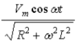
C)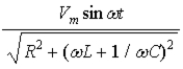
D)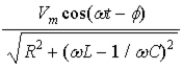
E)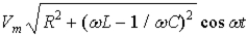
A)
cos ωtB)
C)
D)
E)
Question
Question
Question
Question
Question
The total impedance Z of an RLC circuit driven by an ac voltage source at angular frequency ω is,
A)
B)
C)
D)
E)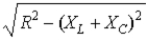
A)
B)
C)
D)
E)
Question
Question
Question
Question
Question
Question
Determine the rms voltage for the circuit. 
A)99 V (rms)
B)140 V (rms)
C)196 V (rms)
D)70 V (rms)
E)110 V (rms)
A)99 V (rms)
B)140 V (rms)
C)196 V (rms)
D)70 V (rms)
E)110 V (rms)
Question
Question
For driving voltage V = Vm sin ωt,the current through the resistor is 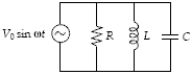
A)Vm sin (ωt + φ)
B)Vm cos (ωt + φ)
C) sin (ωt + φ)
D) sin (ωt + φ)
E) sin ωt
A)Vm sin (ωt + φ)
B)Vm cos (ωt + φ)
C)
sin (ωt + φ)D)
sin (ωt + φ)E)
sin ωt Question
Question
Determine the rms voltage drop across the inductor in the circuit. 
A)11 V
B)27.5 V
C)33 V
D)38.5 V
E)30.5 V
A)11 V
B)27.5 V
C)33 V
D)38.5 V
E)30.5 V
Question
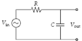
Calculate Vout/Vin for the circuit if R = 2.0 kΩ,C = 0.020 μF and V = 140V sin(50000t).
A)0.02
B)0.45
C)0.80
D)0.98
E)2.2
A)0.02
B)0.45
C)0.80
D)0.98
E)2.2
Question
Determine the resonant frequency of the circuit. 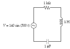
A)159 Hz
B)32 Hz
C)5 Hz
D)500 Hz
E)79.5 Hz
A)159 Hz
B)32 Hz
C)5 Hz
D)500 Hz
E)79.5 Hz
Question
Determine the impedance for the circuit.

A)600 Ω
B)1200 Ω
C)1800 Ω
D)2300 Ω
E)1100 Ω
A)600 Ω
B)1200 Ω
C)1800 Ω
D)2300 Ω
E)1100 Ω
Question
Question
The impedance of the parallel RLC circuit shown is given by 
A)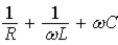
B)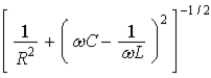
C)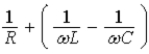
D)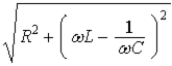
E)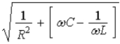
A)
B)
C)
D)
E)
Question
Question
Determine the rms voltage drop across the capacitor in the circuit. 
A)55 V
B)77 V
C)110 V
D)154 V
E)198 V
A)55 V
B)77 V
C)110 V
D)154 V
E)198 V
Question
Question
Question
Determine the rms voltage drop across the resistor in the circuit. 
A)55 V
B)77 V
C)9.9 V
D)5.5 V
E)61 V
A)55 V
B)77 V
C)9.9 V
D)5.5 V
E)61 V
Question
Question
Determine the rms current for the circuit. 
A)55 mA
B)77 mA
C)99 mA
D)0.19 A
E)61 mA
A)55 mA
B)77 mA
C)99 mA
D)0.19 A
E)61 mA
Question
The phase angle between V and I is 
A)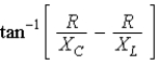
B)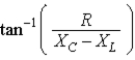
C)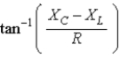
D)
E)
A)
B)
C)
D)
E)
Question
The graphs below represent current and voltage phasors at one instant of time.The solid arrows represent the voltage phasors,ΔVmax,and the dashed arrows represent the current phasors,Imax.The graph which shows the correct relationship between current and voltage phasors for a capacitor in an RC circuit is
A)
B)
C)
D)
E)
A)
B)
C)
D)
E)
Question
Question
The power output,Pout,of an ideal step-up transformer that receives power input,Pin,and which has N1 turns in the primary and N2 turns in the secondary coil is given by
A)Pout = Pin.
B)Pout = Pin.
Pin.
C)Pout = Pin.
Pin.
D)Pout = Pin.
Pin.
E)Pout = Pin.
Pin.
A)Pout = Pin.
B)Pout =
Pin.C)Pout =
Pin.D)Pout =
Pin.E)Pout =
Pin. Question
Question
A 10-μF capacitor in an LC circuit made entirely of superconducting materials (R = 0 Ω)is charged to 100 μC.Then a superconducting switch is closed.At t = 0 s,plate 1 is positively charged and plate 2 is negatively charged.At a later time,Vab = +10 V.At that time,Vdc is 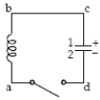
A)0 V.
B)3.54 V.
C)5.0 V.
D)7.07 V.
E)10 V.
A)0 V.
B)3.54 V.
C)5.0 V.
D)7.07 V.
E)10 V.
Question
Question
The graphs below show the phasors ΔVmax and Imax for five RLC series circuits.The solid arrows represent the voltage phasors,ΔV,and the dashed arrows represent the current phasors,Imax.The graph which represents a circuit where the inductive reactance is greater than the capacitive reactance is
A)
B)
C)
D)
E)
A)
B)
C)
D)
E)
Question
Question
Question
The graphs below show a voltage phasor at different instances of time.The voltage phasor which shows the instantaneous value of the voltage with the largest magnitude is
A)
B)
C)
D)
E)
A)
B)
C)
D)
E)
Question
Question
Question
All three circuits shown below have R = 100 Ω,L = 0.1 H and emf ε = (5.0 V)sin (377 t).Which statement regarding the angular resonance frequencies ωA,ωB and ωC is correct? 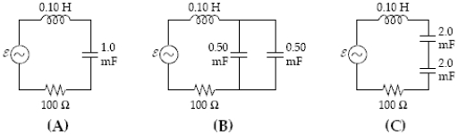
A)ωC > ωA = ωB
B)ωC < ωA = ωB
C)ωA = ωB = ωC
D)ωB < ωA = ωC
E)ωB > ωA = ωC
A)ωC > ωA = ωB
B)ωC < ωA = ωB
C)ωA = ωB = ωC
D)ωB < ωA = ωC
E)ωB > ωA = ωC
Question
All three circuits below have R = 100 Ω,C = 1.0 mF and emf ε = (5.0 V)sin (377 t).The inductors in (B)and (C)are placed sufficiently far apart so that they do not alter one another's inductance.Such inductors add combine like resistors.Which statement regarding the angular resonance frequencies ωA,ωB and ωC is correct? 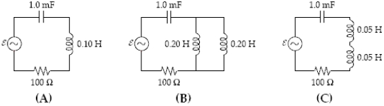
A)ωC > ωA = ωB
B)ωC < ωA = ωB
C)ωA = ωB = ωC
D)ωB < ωA = ωC
E)ωB > ωA = ωC
A)ωC > ωA = ωB
B)ωC < ωA = ωB
C)ωA = ωB = ωC
D)ωB < ωA = ωC
E)ωB > ωA = ωC
Question
The graphs below represent current and voltage phasors at one instant of time.The solid arrows represent the voltage phasors,ΔV,and the dashed arrows represent the current phasors,Imax.The graph which shows the correct relationship between current and voltage phasors for an inductor in an RL circuit is
A)
B)
C)
D)
E)
A)
B)
C)
D)
E)
Question
Question
Question
Question
Question
The graphs below show the phasors ΔVmax and Imax for five RLC series circuits.The solid arrows represent the voltage phasors,ΔV,and the dashed arrows represent the current phasors,Imax.The graph which represents a circuit where the capacitive reactance is greater than the inductive reactance is
A)
B)
C)
D)
E)
A)
B)
C)
D)
E)
Question
Question
Question
Question
Question

Unlock Deck
Sign up to unlock the cards in this deck!
Unlock Deck
Unlock Deck
1/65
Play
Full screen (f)
Deck 33: Alternating-Current Circuits
1
If an R = 1.0-kΩ resistor,a C = 1.0-μF capacitor,and an L = 0.20-H inductor are connected in series with a V = 150 sin (377t)volts source,what is the maximum current delivered by the source?
A)0.007 0 A
B)27 mA
C)54 mA
D)0.31 A
E)0.34 A
A)0.007 0 A
B)27 mA
C)54 mA
D)0.31 A
E)0.34 A
54 mA
2
The inductance of a tuning circuit of an AM radio is 4.00 mH.Find the capacitance of the circuit required for reception at 1 200 kHz.
A)2.10 pF
B)4.40 pF
C)21.2 pF
D)43.4 pF
E)27.6 pF
A)2.10 pF
B)4.40 pF
C)21.2 pF
D)43.4 pF
E)27.6 pF
4.40 pF
3
An ac generator with peak voltage 100 volts is placed across a 10-Ω resistor.What is the average power dissipated?
A)100 W
B)150 W
C)500 W
D)1000 W
E)2000 W
A)100 W
B)150 W
C)500 W
D)1000 W
E)2000 W
500 W
4
An RLC series circuit has R = 100 ohms,C = 25 μF,and L = 0.16 H.For what angular frequency of an ac voltage is the current flow maximum?
A)251 rad/s
B)500 rad/s
C)757 rad/s
D)884 rad/s
E)79.6 rad/s
A)251 rad/s
B)500 rad/s
C)757 rad/s
D)884 rad/s
E)79.6 rad/s
Unlock Deck
Unlock for access to all 65 flashcards in this deck.
Unlock Deck
k this deck
5
An LC circuit is to have resonant oscillations at 5.0 MHz.Find the value of a capacitor which will work with a 1.0-mH inductor.
A)2.0 mF
B)1.0 μF
C)0.020 μF
D)1.0 pF
E)40 pF
A)2.0 mF
B)1.0 μF
C)0.020 μF
D)1.0 pF
E)40 pF
Unlock Deck
Unlock for access to all 65 flashcards in this deck.
Unlock Deck
k this deck
6
A 10.0-μF capacitor is plugged into a 110 V-rms 60.0-Hz voltage source,with an ammeter in series.What is the rms value of the current through the capacitor?
A)0.202 A (rms)
B)0.415 A (rms)
C)0.626 A (rms)
D)0.838 A (rms)
E)0.066 A (rms)
A)0.202 A (rms)
B)0.415 A (rms)
C)0.626 A (rms)
D)0.838 A (rms)
E)0.066 A (rms)
Unlock Deck
Unlock for access to all 65 flashcards in this deck.
Unlock Deck
k this deck
7
Inductive reactance XL is given by
A)Lω
B)L/ω
C)1/Lω
D)ω/L
E)ω2L
A)Lω
B)L/ω
C)1/Lω
D)ω/L
E)ω2L
Unlock Deck
Unlock for access to all 65 flashcards in this deck.
Unlock Deck
k this deck
8
A 2.0-μF capacitor in series with a 2.0-kΩ resistor is connected to a 60-Hz ac source.Calculate the impedance of the circuit.
A)1 500 ohms
B)1 800 ohms
C)2 100 ohms
D)2 400 ohms
E)8 600 ohms
A)1 500 ohms
B)1 800 ohms
C)2 100 ohms
D)2 400 ohms
E)8 600 ohms
Unlock Deck
Unlock for access to all 65 flashcards in this deck.
Unlock Deck
k this deck
9
An electric heater draws an average power of 1100 Watts when plugged into a 110 V-rms outlet.Calculate the resistance of the heater and the rms current.
A)11Ω,10 A (rms)
B)110Ω,10 A (rms)
C)10Ω,11 A (rms)
D)10Ω,110 A (rms)
E)0.09Ω,11 A (rms)
A)11Ω,10 A (rms)
B)110Ω,10 A (rms)
C)10Ω,11 A (rms)
D)10Ω,110 A (rms)
E)0.09Ω,11 A (rms)
Unlock Deck
Unlock for access to all 65 flashcards in this deck.
Unlock Deck
k this deck
10
At what frequency will a 50.0-mH inductor have a reactance XL = 700Ω?
A)352 Hz
B)777 Hz
C)1.25 kHz
D)2.23 kHz
E)14 kHz
A)352 Hz
B)777 Hz
C)1.25 kHz
D)2.23 kHz
E)14 kHz
Unlock Deck
Unlock for access to all 65 flashcards in this deck.
Unlock Deck
k this deck
11
The voltage 8.00 sin (400t)is applied to a series RLC circuit,with R = 200 Ω,L = 0.100 H,and C = 1.00 μF.What are the impedance Z and the phase angle θ?
A)200 Ω,−37.0°
B)566 Ω,+87.0°
C)2 470 Ω,−85.4°
D)2 540 Ω,−88.8°
E)393 Ω,−63.0°
A)200 Ω,−37.0°
B)566 Ω,+87.0°
C)2 470 Ω,−85.4°
D)2 540 Ω,−88.8°
E)393 Ω,−63.0°
Unlock Deck
Unlock for access to all 65 flashcards in this deck.
Unlock Deck
k this deck
12
If the input to an RLC series circuit is V = Vm cos ωt,then the current in the circuit is
A) cos ωt
B)
C)
D)
E)
A)
cos ωtB)
C)
D)
E)
Unlock Deck
Unlock for access to all 65 flashcards in this deck.
Unlock Deck
k this deck
13
A 230000 V-rms powerline carries an average power Pavg = 250 MW a distance of 200 km.If the total resistance of the cables is 10 ohms,what is the resistive power loss?
A)1.0 MW
B)2.5 MW
C)5.4 MW
D)12 MW
E)10 kW
A)1.0 MW
B)2.5 MW
C)5.4 MW
D)12 MW
E)10 kW
Unlock Deck
Unlock for access to all 65 flashcards in this deck.
Unlock Deck
k this deck
14
A 0.500-H inductor is connected into a 110 V-rms 60.0-Hz voltage source,with an ammeter in series.What is the rms value of the current through the inductor?
A)0.189 A (rms)
B)0.292 A (rms)
C)0.584 A (rms)
D)1.19 A (rms)
E)0.093 A (rms)
A)0.189 A (rms)
B)0.292 A (rms)
C)0.584 A (rms)
D)1.19 A (rms)
E)0.093 A (rms)
Unlock Deck
Unlock for access to all 65 flashcards in this deck.
Unlock Deck
k this deck
15
An incandescent lightbulb is rated at 100 Watts when plugged into a 110 V-rms household outlet.Calculate the resistance of the filament and the rms current.
A)12.2Ω,0.91 A (rms)
B)10Ω,1.0 A (rms)
C)110Ω,1.0 A (rms)
D)121Ω,0.91 A (rms)
E)11Ω,1.1 A (rms)
A)12.2Ω,0.91 A (rms)
B)10Ω,1.0 A (rms)
C)110Ω,1.0 A (rms)
D)121Ω,0.91 A (rms)
E)11Ω,1.1 A (rms)
Unlock Deck
Unlock for access to all 65 flashcards in this deck.
Unlock Deck
k this deck
16
Capacitive reactance XC is given by
A)1/ωC
B)ωC
C)ω/C
D)C/ω
E)1/ω2C
A)1/ωC
B)ωC
C)ω/C
D)C/ω
E)1/ω2C
Unlock Deck
Unlock for access to all 65 flashcards in this deck.
Unlock Deck
k this deck
17
The total impedance Z of an RLC circuit driven by an ac voltage source at angular frequency ω is,
A)
B)
C)
D)
E)
A)
B)
C)
D)
E)
Unlock Deck
Unlock for access to all 65 flashcards in this deck.
Unlock Deck
k this deck
18
A high-voltage powerline operates at 500000 V-rms and carries an rms current of 500 A.If the resistance of the cable is 0.050Ω/km,what is the resistive power loss in 200 km of the powerline?
A)250 kW
B)500 kW
C)1 Megawatt
D)2.5 Megawatts
E)250 Megawatts
A)250 kW
B)500 kW
C)1 Megawatt
D)2.5 Megawatts
E)250 Megawatts
Unlock Deck
Unlock for access to all 65 flashcards in this deck.
Unlock Deck
k this deck
19
At what frequency will a 12-μF capacitor have a reactance XC = 300Ω?
A)44 Hz
B)88 Hz
C)180 Hz
D)350 Hz
E)280 Hz
A)44 Hz
B)88 Hz
C)180 Hz
D)350 Hz
E)280 Hz
Unlock Deck
Unlock for access to all 65 flashcards in this deck.
Unlock Deck
k this deck
20
Find the resonant frequency for a series RLC circuit where R = 10Ω,C = 5.00 μF,and L = 2.00 mH.
A)998 Hz
B)1.59 kHz
C)2.45 kHz
D)11.3 kHz
E)2.53 kHz
A)998 Hz
B)1.59 kHz
C)2.45 kHz
D)11.3 kHz
E)2.53 kHz
Unlock Deck
Unlock for access to all 65 flashcards in this deck.
Unlock Deck
k this deck
21
An ideal step-down transformer has 200 primary turns and 50 secondary turns.If 440 volts (rms)is placed across the primary,what is the current in the secondary when the load resistance is 7.00 ohms?
A)3.6 A (rms)
B)7.3 A (rms)
C)11.4 A (rms)
D)15.7 A (rms)
E)12.4 A (rms)
A)3.6 A (rms)
B)7.3 A (rms)
C)11.4 A (rms)
D)15.7 A (rms)
E)12.4 A (rms)
Unlock Deck
Unlock for access to all 65 flashcards in this deck.
Unlock Deck
k this deck
22
A step-up transformer has an input voltage of 110 V (rms).There are 100 turns on the primary and 1500 on the secondary.What is the output voltage?
A)1 600 V (max)
B)1 650 V (rms)
C)3 260 V (max)
D)165 kV (rms)
E)7.3 V (rms)
A)1 600 V (max)
B)1 650 V (rms)
C)3 260 V (max)
D)165 kV (rms)
E)7.3 V (rms)
Unlock Deck
Unlock for access to all 65 flashcards in this deck.
Unlock Deck
k this deck
23
Determine the rms voltage for the circuit.
A)99 V (rms)
B)140 V (rms)
C)196 V (rms)
D)70 V (rms)
E)110 V (rms)
A)99 V (rms)
B)140 V (rms)
C)196 V (rms)
D)70 V (rms)
E)110 V (rms)
Unlock Deck
Unlock for access to all 65 flashcards in this deck.
Unlock Deck
k this deck
24
The primary winding of an electric train transformer has 400 turns and the secondary has 50.If the input voltage is 120V(rms)what is the output voltage?
A)15 V (rms)
B)30 V (rms)
C)60 V (rms)
D)2.4 V (rms)
E)960 V (rms)
A)15 V (rms)
B)30 V (rms)
C)60 V (rms)
D)2.4 V (rms)
E)960 V (rms)
Unlock Deck
Unlock for access to all 65 flashcards in this deck.
Unlock Deck
k this deck
25
For driving voltage V = Vm sin ωt,the current through the resistor is
A)Vm sin (ωt + φ)
B)Vm cos (ωt + φ)
C) sin (ωt + φ)
D) sin (ωt + φ)
E) sin ωt
A)Vm sin (ωt + φ)
B)Vm cos (ωt + φ)
C)
sin (ωt + φ)D)
sin (ωt + φ)E)
sin ωt Unlock Deck
Unlock for access to all 65 flashcards in this deck.
Unlock Deck
k this deck
26
A transformer is to be designed to increase the 30 kV-rms output of a generator to the transmission-line voltage of 345 kV-rms.If the primary winding has 80 turns,how many turns must the secondary have?
A)6
B)70
C)920
D)9200
E)12
A)6
B)70
C)920
D)9200
E)12
Unlock Deck
Unlock for access to all 65 flashcards in this deck.
Unlock Deck
k this deck
27
Determine the rms voltage drop across the inductor in the circuit.
A)11 V
B)27.5 V
C)33 V
D)38.5 V
E)30.5 V
A)11 V
B)27.5 V
C)33 V
D)38.5 V
E)30.5 V
Unlock Deck
Unlock for access to all 65 flashcards in this deck.
Unlock Deck
k this deck
28
Calculate Vout/Vin for the circuit if R = 2.0 kΩ,C = 0.020 μF and V = 140V sin(50000t).
A)0.02
B)0.45
C)0.80
D)0.98
E)2.2
A)0.02
B)0.45
C)0.80
D)0.98
E)2.2
Unlock Deck
Unlock for access to all 65 flashcards in this deck.
Unlock Deck
k this deck
29
Determine the resonant frequency of the circuit.
A)159 Hz
B)32 Hz
C)5 Hz
D)500 Hz
E)79.5 Hz
A)159 Hz
B)32 Hz
C)5 Hz
D)500 Hz
E)79.5 Hz
Unlock Deck
Unlock for access to all 65 flashcards in this deck.
Unlock Deck
k this deck
30
Determine the impedance for the circuit.
A)600 Ω
B)1200 Ω
C)1800 Ω
D)2300 Ω
E)1100 Ω
A)600 Ω
B)1200 Ω
C)1800 Ω
D)2300 Ω
E)1100 Ω
Unlock Deck
Unlock for access to all 65 flashcards in this deck.
Unlock Deck
k this deck
31
A current I = 3 sin (400 t)amperes flows in a series RL circuit in which L = 1 mH and R = 100Ω.What is the average power loss?
A)225 W
B)450 W
C)980 W
D)1.12 kW
E)900 W
A)225 W
B)450 W
C)980 W
D)1.12 kW
E)900 W
Unlock Deck
Unlock for access to all 65 flashcards in this deck.
Unlock Deck
k this deck
32
The impedance of the parallel RLC circuit shown is given by
A)
B)
C)
D)
E)
A)
B)
C)
D)
E)
Unlock Deck
Unlock for access to all 65 flashcards in this deck.
Unlock Deck
k this deck
33
A primary current of 6.0 A exists in an ideal iron-core transformer at a primary voltage of 100 volts.If the current in the secondary is 0.75 A,calculate the output voltage.
A)12.5 V
B)40 V
C)400 V
D)800 V
E)200 V
A)12.5 V
B)40 V
C)400 V
D)800 V
E)200 V
Unlock Deck
Unlock for access to all 65 flashcards in this deck.
Unlock Deck
k this deck
34
Determine the rms voltage drop across the capacitor in the circuit.
A)55 V
B)77 V
C)110 V
D)154 V
E)198 V
A)55 V
B)77 V
C)110 V
D)154 V
E)198 V
Unlock Deck
Unlock for access to all 65 flashcards in this deck.
Unlock Deck
k this deck
35
What is the average power dissipation in a series RC circuit if R = 5.00 kΩ,C = 2.00 μF,and V = 170 cos (300t)?
A)0.930 W
B)2.60 W
C)28.2 W
D)157 W
E)5.20 W
A)0.930 W
B)2.60 W
C)28.2 W
D)157 W
E)5.20 W
Unlock Deck
Unlock for access to all 65 flashcards in this deck.
Unlock Deck
k this deck
36
A series RLC circuit has an impedance of 120Ω and a resistance of 64Ω.What average power is delivered to this circuit when Vrms = 90 volts?
A)36 W
B)100 W
C)192 W
D)360 W
E)12 W
A)36 W
B)100 W
C)192 W
D)360 W
E)12 W
Unlock Deck
Unlock for access to all 65 flashcards in this deck.
Unlock Deck
k this deck
37
Determine the rms voltage drop across the resistor in the circuit.
A)55 V
B)77 V
C)9.9 V
D)5.5 V
E)61 V
A)55 V
B)77 V
C)9.9 V
D)5.5 V
E)61 V
Unlock Deck
Unlock for access to all 65 flashcards in this deck.
Unlock Deck
k this deck
38
What is the average power dissipation in an RLC series circuit with R = 10Ω,L = 0.1 H,C = 10 μF when driven at resonance by a 100 V-rms source?
A)100 W
B)500 W
C)1000 W
D)2 kW
E)700 W
A)100 W
B)500 W
C)1000 W
D)2 kW
E)700 W
Unlock Deck
Unlock for access to all 65 flashcards in this deck.
Unlock Deck
k this deck
39
Determine the rms current for the circuit.
A)55 mA
B)77 mA
C)99 mA
D)0.19 A
E)61 mA
A)55 mA
B)77 mA
C)99 mA
D)0.19 A
E)61 mA
Unlock Deck
Unlock for access to all 65 flashcards in this deck.
Unlock Deck
k this deck
40
The phase angle between V and I is
A)
B)
C)
D)
E)
A)
B)
C)
D)
E)
Unlock Deck
Unlock for access to all 65 flashcards in this deck.
Unlock Deck
k this deck
41
The graphs below represent current and voltage phasors at one instant of time.The solid arrows represent the voltage phasors,ΔVmax,and the dashed arrows represent the current phasors,Imax.The graph which shows the correct relationship between current and voltage phasors for a capacitor in an RC circuit is
A)
B)
C)
D)
E)
A)
B)
C)
D)
E)
Unlock Deck
Unlock for access to all 65 flashcards in this deck.
Unlock Deck
k this deck
42
An alternating current circuit has resistance R,inductance L and capacitance C in series with a voltage source.Which statement is correct?
A)The voltage across the capacitor leads the voltage across the inductor by 90°.
B)The voltage across the inductor leads the voltage across the capacitor by 90°.
C)The voltage across the inductor leads the voltage across the resistor by 180°.
D)The voltage across the inductor is out of phase with the voltage across the capacitor by 180°.
E)Both voltages lead the voltage across the resistor by 90°.
Unlock Deck
Unlock for access to all 65 flashcards in this deck.
Unlock Deck
k this deck
43
The power output,Pout,of an ideal step-up transformer that receives power input,Pin,and which has N1 turns in the primary and N2 turns in the secondary coil is given by
A)Pout = Pin.
B)Pout = Pin.
C)Pout = Pin.
D)Pout = Pin.
E)Pout = Pin.
A)Pout = Pin.
B)Pout =
Pin.C)Pout =
Pin.D)Pout =
Pin.E)Pout =
Pin. Unlock Deck
Unlock for access to all 65 flashcards in this deck.
Unlock Deck
k this deck
44
In a parallel RLC circuit,where IR = IR,max sin(ωt),the current through the capacitor,IC,is
A)IC = −IC,max sin(ωt).
B)IC = IC,max sin(ωt).
C)IC = −IC,max cos(ωt).
D)IC = IC,max cos(ωt).
E)IC = IC,max tan(ωt).
A)IC = −IC,max sin(ωt).
B)IC = IC,max sin(ωt).
C)IC = −IC,max cos(ωt).
D)IC = IC,max cos(ωt).
E)IC = IC,max tan(ωt).
Unlock Deck
Unlock for access to all 65 flashcards in this deck.
Unlock Deck
k this deck
45
A 10-μF capacitor in an LC circuit made entirely of superconducting materials (R = 0 Ω)is charged to 100 μC.Then a superconducting switch is closed.At t = 0 s,plate 1 is positively charged and plate 2 is negatively charged.At a later time,Vab = +10 V.At that time,Vdc is
A)0 V.
B)3.54 V.
C)5.0 V.
D)7.07 V.
E)10 V.
A)0 V.
B)3.54 V.
C)5.0 V.
D)7.07 V.
E)10 V.
Unlock Deck
Unlock for access to all 65 flashcards in this deck.
Unlock Deck
k this deck
46
In a typical transmission line,the current I is very small and the voltage V is very large.A unit length of line has resistance R.For a power line that supplies power to 10000 households,we can conclude that
A)IV = I2R.
B)I = V/R.
C)IV < I2R.
D)IV > I2R.
E)I2R = 0.
A)IV = I2R.
B)I = V/R.
C)IV < I2R.
D)IV > I2R.
E)I2R = 0.
Unlock Deck
Unlock for access to all 65 flashcards in this deck.
Unlock Deck
k this deck
47
The graphs below show the phasors ΔVmax and Imax for five RLC series circuits.The solid arrows represent the voltage phasors,ΔV,and the dashed arrows represent the current phasors,Imax.The graph which represents a circuit where the inductive reactance is greater than the capacitive reactance is
A)
B)
C)
D)
E)
A)
B)
C)
D)
E)
Unlock Deck
Unlock for access to all 65 flashcards in this deck.
Unlock Deck
k this deck
48
The average power input to a series alternating current circuit is minimum when
A)there are only a resistor and capacitor in the circuit.
B)there are only a resistor and inductor in the circuit.
C)there is only a resistor in the circuit.
D)XL = XC and the circuit contains a resistor,an inductor and a capacitor.
E)there is only a capacitor in the circuit.
A)there are only a resistor and capacitor in the circuit.
B)there are only a resistor and inductor in the circuit.
C)there is only a resistor in the circuit.
D)XL = XC and the circuit contains a resistor,an inductor and a capacitor.
E)there is only a capacitor in the circuit.
Unlock Deck
Unlock for access to all 65 flashcards in this deck.
Unlock Deck
k this deck
49
A 60.0-Hz ac generator with a peak voltage of 110 V drives a series RC circuit with R = 10.0 Ω and C = 300 μF.The power factor,cos φ,is
A)−1.00.
B)−0.749.
C)+0.749.
D)+0.834.
E)+1.00.
A)−1.00.
B)−0.749.
C)+0.749.
D)+0.834.
E)+1.00.
Unlock Deck
Unlock for access to all 65 flashcards in this deck.
Unlock Deck
k this deck
50
The graphs below show a voltage phasor at different instances of time.The voltage phasor which shows the instantaneous value of the voltage with the largest magnitude is
A)
B)
C)
D)
E)
A)
B)
C)
D)
E)
Unlock Deck
Unlock for access to all 65 flashcards in this deck.
Unlock Deck
k this deck
51
A 60.0-Hz ac generator with a peak voltage of 110 V drives a series RC circuit with R = 10.0 Ω and C = 300 μF.The impedance is
A)4.68 Ω.
B)8.84 Ω.
C)10.0 Ω.
D)13.4 Ω.
E)18.8 Ω.
A)4.68 Ω.
B)8.84 Ω.
C)10.0 Ω.
D)13.4 Ω.
E)18.8 Ω.
Unlock Deck
Unlock for access to all 65 flashcards in this deck.
Unlock Deck
k this deck
52
A 60.0-Hz ac generator with a peak voltage of 110 V drives a series RC circuit with R = 10.0 Ω and C = 300 μF.The peak current in the circuit is
A)8.24 A.
B)8.84 A.
C)11.0 A.
D)12.4 A.
E)23.5 A.
A)8.24 A.
B)8.84 A.
C)11.0 A.
D)12.4 A.
E)23.5 A.
Unlock Deck
Unlock for access to all 65 flashcards in this deck.
Unlock Deck
k this deck
53
All three circuits shown below have R = 100 Ω,L = 0.1 H and emf ε = (5.0 V)sin (377 t).Which statement regarding the angular resonance frequencies ωA,ωB and ωC is correct?
A)ωC > ωA = ωB
B)ωC < ωA = ωB
C)ωA = ωB = ωC
D)ωB < ωA = ωC
E)ωB > ωA = ωC
A)ωC > ωA = ωB
B)ωC < ωA = ωB
C)ωA = ωB = ωC
D)ωB < ωA = ωC
E)ωB > ωA = ωC
Unlock Deck
Unlock for access to all 65 flashcards in this deck.
Unlock Deck
k this deck
54
All three circuits below have R = 100 Ω,C = 1.0 mF and emf ε = (5.0 V)sin (377 t).The inductors in (B)and (C)are placed sufficiently far apart so that they do not alter one another's inductance.Such inductors add combine like resistors.Which statement regarding the angular resonance frequencies ωA,ωB and ωC is correct?
A)ωC > ωA = ωB
B)ωC < ωA = ωB
C)ωA = ωB = ωC
D)ωB < ωA = ωC
E)ωB > ωA = ωC
A)ωC > ωA = ωB
B)ωC < ωA = ωB
C)ωA = ωB = ωC
D)ωB < ωA = ωC
E)ωB > ωA = ωC
Unlock Deck
Unlock for access to all 65 flashcards in this deck.
Unlock Deck
k this deck
55
The graphs below represent current and voltage phasors at one instant of time.The solid arrows represent the voltage phasors,ΔV,and the dashed arrows represent the current phasors,Imax.The graph which shows the correct relationship between current and voltage phasors for an inductor in an RL circuit is
A)
B)
C)
D)
E)
A)
B)
C)
D)
E)
Unlock Deck
Unlock for access to all 65 flashcards in this deck.
Unlock Deck
k this deck
56
A 60.0-Hz ac generator with a peak voltage of 110 V drives a series RL circuit with R = 10.0 Ω and L = 10.0 mH.The power factor,cos φ,is
A)−1.00.
B)−0.936.
C)+0.943.
D)+0.936.
E)+1.00.
A)−1.00.
B)−0.936.
C)+0.943.
D)+0.936.
E)+1.00.
Unlock Deck
Unlock for access to all 65 flashcards in this deck.
Unlock Deck
k this deck
57
A 60.0-Hz ac generator with a peak voltage of 110 V drives a series RL circuit with R = 10.0 Ω and L = 10.0 mH.The peak current in the circuit is
A)0.963 A.
B)10.3 A.
C)11.0 A.
D)11.9 A.
E)29.2 A.
A)0.963 A.
B)10.3 A.
C)11.0 A.
D)11.9 A.
E)29.2 A.
Unlock Deck
Unlock for access to all 65 flashcards in this deck.
Unlock Deck
k this deck
58
A 60.0-Hz ac generator with a peak voltage of 110 V drives a series RL circuit with R = 10.0 Ω and L = 10.0 mH.The impedance is
A)3.77 Ω.
B)9.26 Ω.
C)10.0 Ω.
D)10.7 Ω.
E)13.8 Ω.
A)3.77 Ω.
B)9.26 Ω.
C)10.0 Ω.
D)10.7 Ω.
E)13.8 Ω.
Unlock Deck
Unlock for access to all 65 flashcards in this deck.
Unlock Deck
k this deck
59
Whenever the alternating current frequency in a series RLC circuit is halved,
A)the inductive reactance is doubled and the capacitive reactance is halved.
B)the inductive reactance is doubled and the capacitive reactance is doubled.
C)the inductive reactance is halved and the capacitive reactance is halved.
D)the inductive reactance is halved and the capacitive reactance is doubled.
E)the reactance of the circuit remains the same.
Unlock Deck
Unlock for access to all 65 flashcards in this deck.
Unlock Deck
k this deck
60
The graphs below show the phasors ΔVmax and Imax for five RLC series circuits.The solid arrows represent the voltage phasors,ΔV,and the dashed arrows represent the current phasors,Imax.The graph which represents a circuit where the capacitive reactance is greater than the inductive reactance is
A)
B)
C)
D)
E)
A)
B)
C)
D)
E)
Unlock Deck
Unlock for access to all 65 flashcards in this deck.
Unlock Deck
k this deck
61
A 10.0-Ω resistor,10.0-mH inductor,and 10.0-μF capacitor are connected in series with a 10.0-kHz voltage source.The rms current through the circuit is 0.200 A.Find the rms voltage drop across each of the 3 elements.
Unlock Deck
Unlock for access to all 65 flashcards in this deck.
Unlock Deck
k this deck
62
In a parallel RLC circuit,where IR = IR,max sin(ωt),the current through the inductor,IL,is
A)IL = −IL,max sin(ωt).
B)IL = IL,max sin(ωt).
C)IL = −IL,max cos(ωt).
D)IL = IL,max cos(ωt).
E)IL = IL,max tan(ωt).
A)IL = −IL,max sin(ωt).
B)IL = IL,max sin(ωt).
C)IL = −IL,max cos(ωt).
D)IL = IL,max cos(ωt).
E)IL = IL,max tan(ωt).
Unlock Deck
Unlock for access to all 65 flashcards in this deck.
Unlock Deck
k this deck
63
Which of the following is true about a diode?
A)A diode causes the voltage to shift in phase by 90°,i.e.,a right angle.
B)A diode has high resistance in one current direction and low resistance in the opposite current direction.
C)A diode can only be used with a transformer.
D)All filter circuits contain a diode.
E)All of the above.
A)A diode causes the voltage to shift in phase by 90°,i.e.,a right angle.
B)A diode has high resistance in one current direction and low resistance in the opposite current direction.
C)A diode can only be used with a transformer.
D)All filter circuits contain a diode.
E)All of the above.
Unlock Deck
Unlock for access to all 65 flashcards in this deck.
Unlock Deck
k this deck
64
An ac power generator produces 50 A (rms)at 3600 V.The voltage is stepped up to 100000 V by an ideal transformer and the energy is transmitted through a long distance power line which has a resistance of 100 ohms.What percentage of the power delivered by the generator is dissipated as heat in the long-distance power line?
Unlock Deck
Unlock for access to all 65 flashcards in this deck.
Unlock Deck
k this deck
65
Suppose the circuit parameters in a series RLC circuit are: L = 1.00 μH,C = 10.0 nF,R = 100 Ω,and the source voltage is 220 V.Determine the resonant frequency of the circuit and the amplitude of the current at resonance.
Unlock Deck
Unlock for access to all 65 flashcards in this deck.
Unlock Deck
k this deck
Unlock Deck
Unlock for access to all 65 flashcards in this deck.


