Basic Engineering Circuit Analysis 11th Edition by David Irwin ,Robert Nelms
Edition 11ISBN: 978-1118539293Basic Engineering Circuit Analysis 11th Edition by David Irwin ,Robert Nelms
Edition 11ISBN: 978-1118539293 Exercise 22
Determine the energy stored in the coupled inductors in Problem 10.39 at t = 1 ms.
Problem 10.39
The currents in the magnetically coupled inductors shown in Fig. P10.39 are known to be
i 1 ( t ) = 8 cos (377 t 20°) mA and
i 2 ( t ) = 4 cos (377 t 50°) mA. The inductor values are L 1 = 2 H, L 2 = 1 H, and k = 0.6. Determine v 1 ( t ) and v 2 ( t ).
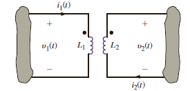
Figure P10.39
Problem 10.39
The currents in the magnetically coupled inductors shown in Fig. P10.39 are known to be
i 1 ( t ) = 8 cos (377 t 20°) mA and
i 2 ( t ) = 4 cos (377 t 50°) mA. The inductor values are L 1 = 2 H, L 2 = 1 H, and k = 0.6. Determine v 1 ( t ) and v 2 ( t ).
Figure P10.39
Explanation Verified
Refer to circuit diagram in Figure P10.3...
Basic Engineering Circuit Analysis 11th Edition by David Irwin ,Robert Nelms
Why don’t you like this exercise?
Other Minimum 8 character and maximum 255 character
Character 255


