Deck 11: Antennas and Radiating Systems
Full screen (f)
Question
Question
Question
Question
Question
Assume that the field in an a × b rectangular aperture in an xy -plane is linearly polarized in the y-direction and that the aperture excitation has a uniform phase and a triangular amplitude distribution
Find (a) the pattern function in the xz -plane, (b) the half-power beamwidth, (c) the location of the first nulls, and (d) the level of the first sidelobes. Compare the results with those obtained in Example 11-13 for uniform field distribution.
Find (a) the pattern function in the xz -plane, (b) the half-power beamwidth, (c) the location of the first nulls, and (d) the level of the first sidelobes. Compare the results with those obtained in Example 11-13 for uniform field distribution.
Question
Question
Question
Question
Question
Question
Question
Question
Question
Question
Question
Question
Do Problem for a uniform-phased cosinusoidal amplitude distribution
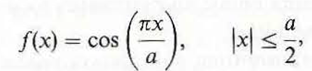
and compare your results with those obtained in Example 11-13 for a uniform field distribution.
Problem:
Assume that the field in an a × b rectangular aperture in an xy -plane is linearly polarized in the y-direction and that the aperture excitation has a uniform phase and a triangular amplitude distribution

Find (a) the pattern function in the xz -plane, (b) the half-power beamwidth, (c) the location of the first nulls, and (d) the level of the first sidelobes. Compare the results with those obtained in Example 11-13 for uniform field distribution.
and compare your results with those obtained in Example 11-13 for a uniform field distribution.
Problem:
Assume that the field in an a × b rectangular aperture in an xy -plane is linearly polarized in the y-direction and that the aperture excitation has a uniform phase and a triangular amplitude distribution
Find (a) the pattern function in the xz -plane, (b) the half-power beamwidth, (c) the location of the first nulls, and (d) the level of the first sidelobes. Compare the results with those obtained in Example 11-13 for uniform field distribution.
Question
Question
Question
Question
Question
Question
Question
Question
Question
Question
Question
Question
Question
Question
Question
Question
Question
Question
Question
Question
Assume the spatial distribution of the current on a very thin center-fed half-wave dipole lying along the z -axis to be I 0 cos z, where = /c - 2 / . Find the charge distribution on the dipole,
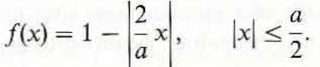
(b) Repeat part (a), assuming the current distribution along the dipole to be a triangular function described by
(b) Repeat part (a), assuming the current distribution along the dipole to be a triangular function described by
Question
Question
Question
Question
Question
Question
Question
Question
Question
Question
Question
Question
Question
Question
Question
Question
Question
Question
Question
Question
Question
Question
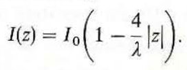
The amplitude of the time-harmonic current distribution on a center-fed short dipole antenna of length 2 h ( h ) can be approximated by a triangular function
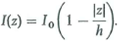
Find (a) the far-zone electric and magnetic field intensities, (b) the radiation resistance, and (c) the directivity.
Find (a) the far-zone electric and magnetic field intensities, (b) the radiation resistance, and (c) the directivity.
Question
Question
Question
Question
Question
Question
Question
Question
Question
Question
Question
Question
Question
Question
Question
Question
Question
Question
Question
Question
Question

Unlock Deck
Sign up to unlock the cards in this deck!
Unlock Deck
Unlock Deck
1/90
Play
Full screen (f)
Deck 11: Antennas and Radiating Systems
1
Obtain the electric field intensity of a Hertzian dipole by finding both A and V and using Eq. (11-2). Check your result with Eqs. (11-16a, b, c).
Consider the expression for electric field intensity in terms of potential functions A and V.
 …… (1)
Where,
 is the angular frequency
Consider the expression for electric field intensity in terms of spherical coordinates.
 …… (2)
Where,
 ,
,
 and
and
 are the spherical components of E
Using equation (1), the spherical components of E.
 …… (3)
 …… (4)
 …… (5)
Consider the phasor representation of vector potential.
 …… (6)
Consider the spherical components of A
 …… (7)
 …… (8)
 …… (9)
Substitute equation (6) in equations (7), (8)
 …… (10)
 …… (11)
Consider the expression of scalar potential for the magnetic dipole shown in Figure 1.
 …… (12)
Where,
 is the electron charge
 …… (13)
 and
and
 are the distance from the charges
 and
and
 to the field
 …… (14)
 …… (15)
 is the permeability of free space
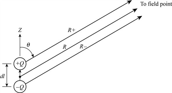 Figure 1
Substitute equations (13), (14), (15) in equations (12)
 Since
Since

 On simplifying
 Substitute
 for
for


 …… (16)
Substitute equations (16), (10) in equations (3).

 …… (17)
Substitute equations (16), (11) in equations (4).

 …… (18)
Substitute equations (16), (9) in equations (5).

 …… (19)
Thus, the electric field intensity of a Hertzian dipole is determined and the results are verified.
…… (1)Where,
is the angular frequencyConsider the expression for electric field intensity in terms of spherical coordinates.
…… (2)Where,
, and are the spherical components of E Using equation (1), the spherical components of E.
…… (3) …… (4) …… (5)Consider the phasor representation of vector potential.
…… (6)Consider the spherical components of A
…… (7) …… (8) …… (9)Substitute equation (6) in equations (7), (8)
…… (10) …… (11)Consider the expression of scalar potential for the magnetic dipole shown in Figure 1.
…… (12)Where,
is the electron charge …… (13) and are the distance from the charges and to the field …… (14) …… (15) is the permeability of free space Figure 1Substitute equations (13), (14), (15) in equations (12)
Since On simplifying Substitute for …… (16)Substitute equations (16), (10) in equations (3).
…… (17)Substitute equations (16), (11) in equations (4).
…… (18)Substitute equations (16), (9) in equations (5).
…… (19)Thus, the electric field intensity of a Hertzian dipole is determined and the results are verified.
2
Repeat parts (a) and (b) of Problem for a small rectangular loop of sides L x and L y. Repeat part (c) for f = 1 (MHz), L x = L y = 2b = 1 (m), a = 3 (mm), and compare results.
A time-harmonic uniform current I 0 cos t flows in a small circular loop of radius b ( ) lying in the xy -plane.
a) Find the radiation resistance R r of the magnetic dipole.
b) Obtain an expression for its radiation efficiency n r if the loop is made of copper wire of radius a ,
c) Calculate R r and n f for f = 1 (MHz), b = 50 (cm), and a = 3 (mm).
d) Rework part (c) if the loop has ten closely wound insulated turns.
(a)
Consider the formula for radiation resistance
 of the small rectangular loop antenna.
 …… (1)
Where,
 is denoted as radiation resistance.
Substitute
 for
for
 in equation (1).


 …… (2)
Hence, the radiation resistance
 of small rectangular loop antenna is
 (b)
(b)
Consider the formula for total input power.
 …… (3)
Where,
 is denoted as input power,
 is denoted as power loss,
 is denoted as radiated power.
Consider the formula for power loss.
 …… (4)
Where,
 is denoted as loss resistance.
Consider the formula for radiated power.
 …… (5)
Where,
 is denoted as radiation resistance.
Consider the formula for radiation efficiency.
 …… (6)
Where,
 is denoted as the Radiation efficiency.
Substitute equation (3) in equation (6),

 …… (7)
Consider the formula for loss resistance in a copper wire.
 …… (8)
Where,
 is denoted as surface resistance.
dl is denoted as length of antenna.
a is denoted as radius of the copper wire
Consider the condition
 and
and
 in equation (8) rewritten as
 …… (9)
Consider the formula for the surface resistance.
 …… (10)
Where,
 is denoted as conductivity of the copper
 .
.
f is denoted as operating frequency.
Hence, the expression for radiation efficiency is
 (c)
(c)
Substitute
 for
for
 , 1MHz for f and
 for
for
 in equation (10).
 Convert millimeter to meter.
 Consider the formula for
 is,
is,
 Substitute
 for c and 1 MHz for f.
 Calculate the value of

 Thus, the value of
 is
is
 .
.
Consider the antenna length (4) for dl in square loop.
Substitute
 for
for
 ,
,
 for a and
 for b in equation (8).
 Substitute
 for
for
 , 1 for
 and 1 for
 in equation (2).
 Substitute
 for
for
 and
and
 for
for
 in equation (7).
 Hence, the radiation resistance in
 and radiation efficiency is
 .
.
Comparison between circular loop and rectangular loop antenna is tabulated in table 1
Table 1
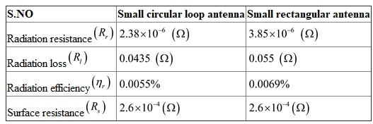 Hence, the comparison of circular loop and rectangular loop antenna is tabulated.
Consider the formula for radiation resistance
of the small rectangular loop antenna. …… (1)Where,
is denoted as radiation resistance.Substitute
for in equation (1). …… (2)Hence, the radiation resistance
of small rectangular loop antenna is (b)Consider the formula for total input power.
…… (3)Where,
is denoted as input power, is denoted as power loss, is denoted as radiated power.Consider the formula for power loss.
…… (4)Where,
is denoted as loss resistance.Consider the formula for radiated power.
…… (5)Where,
is denoted as radiation resistance.Consider the formula for radiation efficiency.
…… (6)Where,
is denoted as the Radiation efficiency.Substitute equation (3) in equation (6),
…… (7)Consider the formula for loss resistance in a copper wire.
…… (8)Where,
is denoted as surface resistance.dl is denoted as length of antenna.
a is denoted as radius of the copper wire
Consider the condition
and in equation (8) rewritten as …… (9)Consider the formula for the surface resistance.
…… (10)Where,
is denoted as conductivity of the copper .f is denoted as operating frequency.
Hence, the expression for radiation efficiency is
(c) Substitute
for , 1MHz for f and for in equation (10). Convert millimeter to meter. Consider the formula for is, Substitute for c and 1 MHz for f. Calculate the value of Thus, the value of is .Consider the antenna length (4) for dl in square loop.
Substitute
for , for a and for b in equation (8). Substitute for , 1 for and 1 for in equation (2). Substitute for and for in equation (7). Hence, the radiation resistance in and radiation efficiency is .Comparison between circular loop and rectangular loop antenna is tabulated in table 1
Table 1
Hence, the comparison of circular loop and rectangular loop antenna is tabulated. 3
For a five-element broadside binomial array:
a) Determine the relative excitation amplitudes in the array elements.
b) Plot the array factor for d = /2.
c) Determine the half-power beamwidth and compare it with that of a five-element uniform array having the same element spacings.
a) Determine the relative excitation amplitudes in the array elements.
b) Plot the array factor for d = /2.
c) Determine the half-power beamwidth and compare it with that of a five-element uniform array having the same element spacings.
(a)
The excitation amplitudes vary according to the coefficients of binomial expansion
 For five elements,
 Hence, relative excitation amplitudes in the array elements are
 .
.
(b)
Plot for array factor for
 :
:
In a binomial array of N elements the array factor is binomial function. This is given as
 .
.
It is known that the normalized pattern function is equal to the normalized array factor
 .
.
Write the expression for
 .
.
 For
For
 , calculate
 .
.
 For five elements, calculate
 .
.
 Draw the pattern function for
 .
.
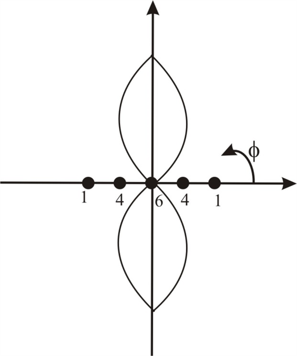 Figure 1
(c)
Consider the following:
 Calculate the half-power beam width.
 Therefore, the half-power beam width is
 .
.
For uniform array, the normalized array factor is,

 Calculate the half-power beam width for 5-element uniform array with
 spacing.
 Therefore, the half-power beam width for 5-element uniform array is
 .
.
The half-power band width is
 where as the half-power beam width for 5-element uniform array with
 spacing is
 .
.
Therefore, the half-power band width is less for 5-element uniform array.
The excitation amplitudes vary according to the coefficients of binomial expansion
For five elements, Hence, relative excitation amplitudes in the array elements are .(b)
Plot for array factor for
:In a binomial array of N elements the array factor is binomial function. This is given as
.It is known that the normalized pattern function is equal to the normalized array factor
. Write the expression for
. For , calculate . For five elements, calculate . Draw the pattern function for . Figure 1(c)
Consider the following:
Calculate the half-power beam width. Therefore, the half-power beam width is .For uniform array, the normalized array factor is,
Calculate the half-power beam width for 5-element uniform array with spacing. Therefore, the half-power beam width for 5-element uniform array is .The half-power band width is
where as the half-power beam width for 5-element uniform array with spacing is . Therefore, the half-power band width is less for 5-element uniform array.
4
Communication is to be established between two stations 1.5 (km) apart that operate at 300 (MHz). Each is equipped with a half-wave dipole.
a) If 100 (W) is transmitted from one station, how much power is received by a matched load at the other station
b) Repeat part (a) assuming that both antennas are Hertzian dipoles.
a) If 100 (W) is transmitted from one station, how much power is received by a matched load at the other station
b) Repeat part (a) assuming that both antennas are Hertzian dipoles.
Unlock Deck
Unlock for access to all 90 flashcards in this deck.
Unlock Deck
k this deck
5
Assume that the field in an a × b rectangular aperture in an xy -plane is linearly polarized in the y-direction and that the aperture excitation has a uniform phase and a triangular amplitude distribution
Find (a) the pattern function in the xz -plane, (b) the half-power beamwidth, (c) the location of the first nulls, and (d) the level of the first sidelobes. Compare the results with those obtained in Example 11-13 for uniform field distribution.
Find (a) the pattern function in the xz -plane, (b) the half-power beamwidth, (c) the location of the first nulls, and (d) the level of the first sidelobes. Compare the results with those obtained in Example 11-13 for uniform field distribution.
Unlock Deck
Unlock for access to all 90 flashcards in this deck.
Unlock Deck
k this deck
6
What is an equiangular spiral Why does it have broadband properties
Unlock Deck
Unlock for access to all 90 flashcards in this deck.
Unlock Deck
k this deck
7
Why are antennas important for wireless communication over long distances
Unlock Deck
Unlock for access to all 90 flashcards in this deck.
Unlock Deck
k this deck
8
What are radiation fields
Unlock Deck
Unlock for access to all 90 flashcards in this deck.
Unlock Deck
k this deck
9
Define radiation resistance of an antenna.
Unlock Deck
Unlock for access to all 90 flashcards in this deck.
Unlock Deck
k this deck
10
What is meant by the normalized array factor of an antenna array How is it different from the pattern function of the individual antennas
Unlock Deck
Unlock for access to all 90 flashcards in this deck.
Unlock Deck
k this deck
11
What is a frequency-scanning array
Unlock Deck
Unlock for access to all 90 flashcards in this deck.
Unlock Deck
k this deck
12
What is a log-periodic antenna
Unlock Deck
Unlock for access to all 90 flashcards in this deck.
Unlock Deck
k this deck
13
A small filamentary rectangular loop of dimensions L x and L y lies in the xy -plane with its center at the origin and sides parallel to the x - and y -axes. The loop carries a current i(t) = I 0 cos t. Assuming L x and L y to be much less than the wavelength, find the instantaneous expressions for the following quantities at a point in the far zone:
a) vector magnetic potential A ,
b) electric field intensity E ,
c) magnetic field intensity H.
Compare the results in parts (b) and (c) with Eqs. (11-30a) and (11 -30b), respectively.
a) vector magnetic potential A ,
b) electric field intensity E ,
c) magnetic field intensity H.
Compare the results in parts (b) and (c) with Eqs. (11-30a) and (11 -30b), respectively.
Unlock Deck
Unlock for access to all 90 flashcards in this deck.
Unlock Deck
k this deck
14
Use the total field expressions in Eqs. (11-15) and (11-16) to find the time-average power radiated by a Hertzian dipole, and compare it with the result in Eq. (11-43) using only the far-zone fields.
Unlock Deck
Unlock for access to all 90 flashcards in this deck.
Unlock Deck
k this deck
15
For a uniform linear array of 12 elements spaced /2 apart:
a) Sketch the normalized array pattern |A( )| in Eq. (11-89) versus .
b) Find the widths of the main beam at half-power points and between the first nulls when the array is operated in the broadside mode.
c) Repeat part (b) for an endfire operation.
a) Sketch the normalized array pattern |A( )| in Eq. (11-89) versus .
b) Find the widths of the main beam at half-power points and between the first nulls when the array is operated in the broadside mode.
c) Repeat part (b) for an endfire operation.
Unlock Deck
Unlock for access to all 90 flashcards in this deck.
Unlock Deck
k this deck
16
Show that three satellites equally spaced around the geosynchronous orbit in the equatorial plane would cover almost the entire earth's surface. Explain why the polar regions are not covered. (b) Assuming the main beam of the radiation pattern of the satellite antenna to have the shape of a circular cone that just covers the earth with no spillover, find a relation between the main-lobe beamwidth and the directive gain of the antenna.
Unlock Deck
Unlock for access to all 90 flashcards in this deck.
Unlock Deck
k this deck
17
Do Problem for a uniform-phased cosinusoidal amplitude distribution
and compare your results with those obtained in Example 11-13 for a uniform field distribution.
Problem:
Assume that the field in an a × b rectangular aperture in an xy -plane is linearly polarized in the y-direction and that the aperture excitation has a uniform phase and a triangular amplitude distribution
Find (a) the pattern function in the xz -plane, (b) the half-power beamwidth, (c) the location of the first nulls, and (d) the level of the first sidelobes. Compare the results with those obtained in Example 11-13 for uniform field distribution.
Unlock Deck
Unlock for access to all 90 flashcards in this deck.
Unlock Deck
k this deck
18
Explain the principle of operation of log-periodic dipole arrays.
Unlock Deck
Unlock for access to all 90 flashcards in this deck.
Unlock Deck
k this deck
19
State the procedure for finding the electromagnetic field due to an assumed time-harmonic current distribution on an antenna structure.
Unlock Deck
Unlock for access to all 90 flashcards in this deck.
Unlock Deck
k this deck
20
Define antenna pattern.
Unlock Deck
Unlock for access to all 90 flashcards in this deck.
Unlock Deck
k this deck
21
Discuss how the ratios (a/ ) and (dl/ ) of a Hertzian dipole affect its radiation resistance and radiation efficiency.
Unlock Deck
Unlock for access to all 90 flashcards in this deck.
Unlock Deck
k this deck
22
State the principle of pattern multiplication.
Unlock Deck
Unlock for access to all 90 flashcards in this deck.
Unlock Deck
k this deck
23
What are the important consequences of reciprocity relations concerning antennas that operate in the transmitting and receiving modes
Unlock Deck
Unlock for access to all 90 flashcards in this deck.
Unlock Deck
k this deck
24
Give three examples of aperture radiators.
Unlock Deck
Unlock for access to all 90 flashcards in this deck.
Unlock Deck
k this deck
25
A composite antenna consists of an elemental Hertzian electric dipole of length L along the z -axis and an elemental magnetic dipole of area S lying in the xy -plane. Equal time-harmonic currents of amplitude I 0 and angular frequency flow in the dipoles.
a) Verify that the far field of the composite antenna is elliptically polarized.
b) Determine the condition for circular polarization.
a) Verify that the far field of the composite antenna is elliptically polarized.
b) Determine the condition for circular polarization.
Unlock Deck
Unlock for access to all 90 flashcards in this deck.
Unlock Deck
k this deck
26
Sketch the polar radiation pattern versus for a thin dipole antenna of total length 2 h = 1.25 . Determine the width of the main beam between the first nulls.
Unlock Deck
Unlock for access to all 90 flashcards in this deck.
Unlock Deck
k this deck
27
For a uniform linear array with a large number of elements the denominator sin ( /2) in Eq. (11-89) remains small over a large portion of the normalized array pattern near the main beam and can be approximated by ( /2). Use this approximation to determine the directivity of the array of a large uniform array with many elements.
Unlock Deck
Unlock for access to all 90 flashcards in this deck.
Unlock Deck
k this deck
28
The antenna at the earth station of a satellite communication link having a gain of 55 (dB) at 14 (GHz) is aimed at a geostationary satellite 36,500 (km) away. Assume that the antenna on the satellite has a gain of 35 (dB) in transmitting the signal back toward the earth station at 12 (GHz). The minimum usable signal is 8 (pW).
a) Neglecting antenna ohmic and mismatch losses, find the minimum satellite transmitting power required.
b) Find the peak transmitting pulse power needed at the earth station in order to detect the satellite as a passive object, assuming the backscatter cross section of the satellite including its solar panels as 25 (m 2 ) and the minimum detectable return pulse power to be 0.5 (pW).
Unlock Deck
Unlock for access to all 90 flashcards in this deck.
Unlock Deck
k this deck
29
Define effective area of an antenna.
Unlock Deck
Unlock for access to all 90 flashcards in this deck.
Unlock Deck
k this deck
30
For a linearly polarized aperture field with uniform phase, what is the relation between the aperture's field distribution and the pattern function
Unlock Deck
Unlock for access to all 90 flashcards in this deck.
Unlock Deck
k this deck
31
What is a Hertzian dipole
Unlock Deck
Unlock for access to all 90 flashcards in this deck.
Unlock Deck
k this deck
32
Describe the E -plane and H -plane patterns of a Hertzian dipole.
Unlock Deck
Unlock for access to all 90 flashcards in this deck.
Unlock Deck
k this deck
33
Describe the radiation pattern of a half-wave dipole antenna.
Unlock Deck
Unlock for access to all 90 flashcards in this deck.
Unlock Deck
k this deck
34
State the difference between a broadside array and an endfire array.
Unlock Deck
Unlock for access to all 90 flashcards in this deck.
Unlock Deck
k this deck
35
What is the universal constant that is the ratio of the directive gain and the effective area of an antenna
Unlock Deck
Unlock for access to all 90 flashcards in this deck.
Unlock Deck
k this deck
36
What is the directivity of an aperture having an area A and a linearly polarized uniform field distribution at frequency f
Unlock Deck
Unlock for access to all 90 flashcards in this deck.
Unlock Deck
k this deck
37
Assume the spatial distribution of the current on a very thin center-fed half-wave dipole lying along the z -axis to be I 0 cos z, where = /c - 2 / . Find the charge distribution on the dipole,
(b) Repeat part (a), assuming the current distribution along the dipole to be a triangular function described by
(b) Repeat part (a), assuming the current distribution along the dipole to be a triangular function described by
Unlock Deck
Unlock for access to all 90 flashcards in this deck.
Unlock Deck
k this deck
38
Assuming a triangular current distribution on a center-fed /6 dipole (h = /12), find an expression for its effective length. What is its maximum value
Unlock Deck
Unlock for access to all 90 flashcards in this deck.
Unlock Deck
k this deck
39
Using the graph in Fig. 11-15(a) for the normalized array factor of a five-element broadside linear array with d = /2 and amplitude ratios 1:2:3:2:1, plot the polar radiation pattern for d = /4 and = - /2.
Unlock Deck
Unlock for access to all 90 flashcards in this deck.
Unlock Deck
k this deck
40
A transmitting vertical half-wave dipole 60 (m) above the ground radiates 400 (W) at 100 (MHz). Assume the ground to be perfectly conducting.
a) Calculate the power available at a vertical half-wave receiving antenna 50 (km) away at a height 30 (m) above the ground.
b) At a distance 50 (km) from the transmitting antenna, where (at what altitudes) would there be a null field
a) Calculate the power available at a vertical half-wave receiving antenna 50 (km) away at a height 30 (m) above the ground.
b) At a distance 50 (km) from the transmitting antenna, where (at what altitudes) would there be a null field
Unlock Deck
Unlock for access to all 90 flashcards in this deck.
Unlock Deck
k this deck
41
Define backscatter cross section of an object.
Unlock Deck
Unlock for access to all 90 flashcards in this deck.
Unlock Deck
k this deck
42
Describe the manner in which the beamwidth in a principal plane of a rectangular aperture with a uniform field distribution depends on its dimensions.
Unlock Deck
Unlock for access to all 90 flashcards in this deck.
Unlock Deck
k this deck
43
What constitutes an elemental magnetic dipole
Unlock Deck
Unlock for access to all 90 flashcards in this deck.
Unlock Deck
k this deck
44
Define beamwidth of an antenna pattern.
Unlock Deck
Unlock for access to all 90 flashcards in this deck.
Unlock Deck
k this deck
45
What are the radiation resistance and directivity of a half-wave dipole antenna
Unlock Deck
Unlock for access to all 90 flashcards in this deck.
Unlock Deck
k this deck
46
What is a binomial array What are the relative excitation amplitudes of a six-element binomial array
Unlock Deck
Unlock for access to all 90 flashcards in this deck.
Unlock Deck
k this deck
47
Explain the principle of radar.
Unlock Deck
Unlock for access to all 90 flashcards in this deck.
Unlock Deck
k this deck
48
Assume that a linearly polarized constant excitation field exists in a rectangular aperture with width b and a circular aperture with diameter D = b. Compare the main-lobe beamwidths and the first sidelobe levels of their radiation patterns.
Unlock Deck
Unlock for access to all 90 flashcards in this deck.
Unlock Deck
k this deck
49
A 1-(MHz) uniform current flows in a vertical antenna of length 15 (m). The antenna is a center-fed copper rod having a radius of 2 (cm). Find:
a) the radiation resistance,
b) the radiation efficiency, and
c) the maximum electric field intensity at a distance of 20 (km) if the radiated power of the antenna is 1.6 (kW).
a) the radiation resistance,
b) the radiation efficiency, and
c) the maximum electric field intensity at a distance of 20 (km) if the radiated power of the antenna is 1.6 (kW).
Unlock Deck
Unlock for access to all 90 flashcards in this deck.
Unlock Deck
k this deck
50
5 (MHz) uniform plane wave having a peak electric field intensity E 0 is incident on a half-wave dipole at an angle .
a) Find the expression for the open-circuit voltage V oc at the terminals of the dipole.
b) If the dipole is connected to a matched load, what is the maximum power P L delivered to the load
c) Calculate V oc and P L for E 0 = 50 (mV/m) and for = /2 and /4.
a) Find the expression for the open-circuit voltage V oc at the terminals of the dipole.
b) If the dipole is connected to a matched load, what is the maximum power P L delivered to the load
c) Calculate V oc and P L for E 0 = 50 (mV/m) and for = /2 and /4.
Unlock Deck
Unlock for access to all 90 flashcards in this deck.
Unlock Deck
k this deck
51
Letting = exp (j ), we can write the array factor of an equally spaced array as a polynomial, A( ), in , and many characteristics of the array pattern can be estimated by examining the distribution of the zeros of the array polynomial on a unit circle. In general, an N -element linear array has N - 1 zeros, 0m (m = 1,2,..., N - 1), distributed around the unit circle. Find A( ) and locate all 0m on a unit circle for the following linear arrays:
a) a two-element array,
b) a three-element binomial array,
c) a five-element uniform array,
d) a five-element array having amplitude ratios 1:2:3:2:1 (as in Example 11-9).
e) Based on the locations of 0m for the two arrays in parts (c) and (d), explain why the pattern for the array in part (d) has lower sidelobes but a wider beamwidth.
Unlock Deck
Unlock for access to all 90 flashcards in this deck.
Unlock Deck
k this deck
52
The current along an isolated and terminated traveling-wave antenna of length L is given as
I(z) = I 0 e-j z.
a) Find the far-zone vector potential, A(R, ).
b) Determine H (R, ) and E(R, 0) from A(R, ).
c) Sketch the radiation pattern for L = /2.
I(z) = I 0 e-j z.
a) Find the far-zone vector potential, A(R, ).
b) Determine H (R, ) and E(R, 0) from A(R, ).
c) Sketch the radiation pattern for L = /2.
Unlock Deck
Unlock for access to all 90 flashcards in this deck.
Unlock Deck
k this deck
53
What does the Friis transmission formula say
Unlock Deck
Unlock for access to all 90 flashcards in this deck.
Unlock Deck
k this deck
54
Define the near zone and the far zone of an antenna.
Unlock Deck
Unlock for access to all 90 flashcards in this deck.
Unlock Deck
k this deck
55
Define sidelobe level of an antenna pattern.
Unlock Deck
Unlock for access to all 90 flashcards in this deck.
Unlock Deck
k this deck
56
What is the image of a horizontal dipole over a conducting ground
Unlock Deck
Unlock for access to all 90 flashcards in this deck.
Unlock Deck
k this deck
57
Is the radiation pattern of all linear binomial arrays sidelobeless Explain.
Unlock Deck
Unlock for access to all 90 flashcards in this deck.
Unlock Deck
k this deck
58
Define path gain factor concerning wave propagation near the earth's surface.
Unlock Deck
Unlock for access to all 90 flashcards in this deck.
Unlock Deck
k this deck
59
The amplitude of the time-harmonic current distribution on a center-fed short dipole antenna of length 2 h ( h ) can be approximated by a triangular function
Find (a) the far-zone electric and magnetic field intensities, (b) the radiation resistance, and (c) the directivity.
Find (a) the far-zone electric and magnetic field intensities, (b) the radiation resistance, and (c) the directivity.
Unlock Deck
Unlock for access to all 90 flashcards in this deck.
Unlock Deck
k this deck
60
Two elemental dipole antennas, each of length 2 h ( h ), are aligned colinearly along the z -axis with their centers spaced a distance d ( d 2 h ) apart. The excitations in the two antennas are of equal amplitude and equal phase.
a) Write the general expression for the far-zone electric field of this two-element colinear array.
b) Plot the normalized E -plane pattern for d = /2.
c) Repeat part (b) for d = .
a) Write the general expression for the far-zone electric field of this two-element colinear array.
b) Plot the normalized E -plane pattern for d = /2.
c) Repeat part (b) for d = .
Unlock Deck
Unlock for access to all 90 flashcards in this deck.
Unlock Deck
k this deck
61
Obtain the pattern function of a uniformly excited rectangular array of N 1 × N 2 parallel half-wave dipoles. Assume that the dipoles are parallel to the z -axis and their centers are spaced d 1 and d 2 apart in the x - and y -directions, respectively.
Unlock Deck
Unlock for access to all 90 flashcards in this deck.
Unlock Deck
k this deck
62
A turnstile antenna consists of two perpendicular half-wave dipoles, one (antenna A) lying along the x -axis and the other (antenna B) along the y-axis. The output of antenna B, after a 90° phase retardation, is combined with that of antenna A. A right-hand elliptically polarized plane wave E i = E 0 ( a x + a y jp) exp (jkz) is incident on the antennas.
a) Determine the open-circuit voltage at the output terminals of the turnstile antenna. What is its value if p = 1
b) Repeat part (a) for a left-hand elliptically polarized incident wave E i = E 0 ( a x - a y jp) exp (jkz).
c) Repeat part (a) for a linearly polarized incident wave E i = a x E 0 exp (jkz).
(Hint: Find the complex effective length of the turnstile antenna and use Eq. 11-76.)
Unlock Deck
Unlock for access to all 90 flashcards in this deck.
Unlock Deck
k this deck
63
In what essential ways does the radiation pattern of a long traveling-wave antenna differ from that of an unterminated dipole antenna
Unlock Deck
Unlock for access to all 90 flashcards in this deck.
Unlock Deck
k this deck
64
Why are the near-zone fields called quasi-static fields
Unlock Deck
Unlock for access to all 90 flashcards in this deck.
Unlock Deck
k this deck
65
Define radiation intensity.
Unlock Deck
Unlock for access to all 90 flashcards in this deck.
Unlock Deck
k this deck
66
What are the radiation resistance and directivity of a vertical quarter-wave monopole over a conducting ground
Unlock Deck
Unlock for access to all 90 flashcards in this deck.
Unlock Deck
k this deck
67
In the radiation pattern of a uniform linear array of many elements, how many decibels down from the principal maximum are the first sidelobes
Unlock Deck
Unlock for access to all 90 flashcards in this deck.
Unlock Deck
k this deck
68
What is the essential difference between the radiation characteristics of a helical antenna and a dipole antenna
Unlock Deck
Unlock for access to all 90 flashcards in this deck.
Unlock Deck
k this deck
69
The transmitting antenna of a radio navigation system is a vertical metal mast 40 (m) in height insulated from the earth. A 180 (kHz) source sends a current having an amplitude of 100 (A) into the base of the mast. Assuming the current amplitude in the antenna to decrease linearly toward zero at the top of the mast and the earth to be a perfectly conducting plane, determine:
a) the effective length of the antenna,
b) the maximum field intensity at a distance 160 (km) from the antenna,
c) the time-average radiated power,
d) the radiation resistance.
a) the effective length of the antenna,
b) the maximum field intensity at a distance 160 (km) from the antenna,
c) the time-average radiated power,
d) the radiation resistance.
Unlock Deck
Unlock for access to all 90 flashcards in this deck.
Unlock Deck
k this deck
70
A horizontal elemental electric dipole of length dl and carrying a time-harmonic current of amplitude I 0 in the + y-direction is situated at a distance d above a perfectly conducting ground. Find its pattern functions
(a) in the xy-plane,
(b) in the xz-plane, and
(c) in the yz-plane.
(d) Sketch the patterns for parts (a), (b), and (c) for d = /4.
(a) in the xy-plane,
(b) in the xz-plane, and
(c) in the yz-plane.
(d) Sketch the patterns for parts (a), (b), and (c) for d = /4.
Unlock Deck
Unlock for access to all 90 flashcards in this deck.
Unlock Deck
k this deck
71
Assume that a linearly polarized plane electromagnetic wave is incident on a halfwave dipole, as in Fig. 11-8.
a) Obtain an expression for the effective area, A e ( ).
b) Calculate the maximum value of A e for 100 (MHz).
a) Obtain an expression for the effective area, A e ( ).
b) Calculate the maximum value of A e for 100 (MHz).
Unlock Deck
Unlock for access to all 90 flashcards in this deck.
Unlock Deck
k this deck
72
A helical antenna operating in the normal mode has N turns with diameter 2b and interturn spacing s. Both 2b and s are very small in comparison to /N and are adjusted to radiate circularly polarized waves. Find:
a) its directive gain and directivity,
b) its radiation resistance.
a) its directive gain and directivity,
b) its radiation resistance.
Unlock Deck
Unlock for access to all 90 flashcards in this deck.
Unlock Deck
k this deck
73
What are the two different operating modes of a helical antenna Explain.
Unlock Deck
Unlock for access to all 90 flashcards in this deck.
Unlock Deck
k this deck
74
Explain how the magnitude of far fields varies with distance.
Unlock Deck
Unlock for access to all 90 flashcards in this deck.
Unlock Deck
k this deck
75
Define directive gain and directivity of an antenna.
Unlock Deck
Unlock for access to all 90 flashcards in this deck.
Unlock Deck
k this deck
76
Define the effective length of a linear antenna for transmitting. Upon what factors does it depend
Unlock Deck
Unlock for access to all 90 flashcards in this deck.
Unlock Deck
k this deck
77
How can the sidelobes of an equally spaced linear array be made lower than those of a uniform linear array
Unlock Deck
Unlock for access to all 90 flashcards in this deck.
Unlock Deck
k this deck
78
What is a Yagi-Uda antenna
Unlock Deck
Unlock for access to all 90 flashcards in this deck.
Unlock Deck
k this deck
79
Starting from Maxwell's equations, derive the nonhomogeneous wave equations (a) for E , and (b) for H in a simple medium.
Unlock Deck
Unlock for access to all 90 flashcards in this deck.
Unlock Deck
k this deck
80
A time-harmonic uniform current I 0 cos t flows in a small circular loop of radius b ( ) lying in the xy -plane.
a) Find the radiation resistance R r of the magnetic dipole.
b) Obtain an expression for its radiation efficiency n r if the loop is made of copper wire of radius a ,
c) Calculate R r and n f for f = 1 (MHz), b = 50 (cm), and a = 3 (mm).
d) Rework part (c) if the loop has ten closely wound insulated turns.
Unlock Deck
Unlock for access to all 90 flashcards in this deck.
Unlock Deck
k this deck
Unlock Deck
Unlock for access to all 90 flashcards in this deck.


