Deck 7: Tension, Compression and Shear
Full screen (f)
Question
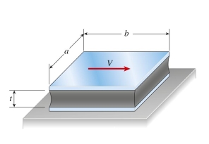
An elastomeric bearing pad is subjected to a shear force V during a static loading test. The pad has dimensions a 5 150 mm and b 5 225 mm, and thickness t 5 55 mm. The lateral displacement of the top plate with respect to the
Bottom plate is 14 mm under a load P 5 16 kN. The shear modulus of elasticity G of the elastomer is approximately:
Bottom plate is 14 mm under a load P 5 16 kN. The shear modulus of elasticity G of the elastomer is approximately:
Question


Question
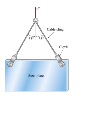
steel plate weighing 27 kN is hoisted by a cable sling that has a clevis at each end. The pins through the clevises are 22 mm in diameter. Each half of the cable is at an angle of 35° to the vertical. The average shear  stress in each pin is approximately:
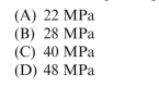
stress in each pin is approximately: Question
aluminum bar (  0.33) of diameter 50 mm cannot exceed a diameter of 50.1 mm when compressed by axial force P. The maximum acceptable compressive load P is approximately:
(A) 190 kN
(B) 200 kN
(C) 470 kN
(D) 860 kN
0.33) of diameter 50 mm cannot exceed a diameter of 50.1 mm when compressed by axial force P. The maximum acceptable compressive load P is approximately:(A) 190 kN
(B) 200 kN
(C) 470 kN
(D) 860 kN
Question
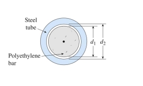
polyethylene bar (  0.4) of diameter 80 mm is inserted in a steel tube of inside diameter 80.2 mm and then compressed by axial force P. The gap between steel tube and polyethylene bar will close when compressive load P is approximately:
(A) 18 kN
(B) 25 kN
(C) 44 kN
(D) 60 kN
0.4) of diameter 80 mm is inserted in a steel tube of inside diameter 80.2 mm and then compressed by axial force P. The gap between steel tube and polyethylene bar will close when compressive load P is approximately:(A) 18 kN
(B) 25 kN
(C) 44 kN
(D) 60 kN
Question
Two flanged shafts are connected by eight 18-mm bolts. The diameter of the bolt circle is 240 mm. The allowable shear stress in the bolts is 90 MPa. Ignore friction between the flange plates. The maximum value of  torque
  is approximately:
(A) 19 kN ∙ m
(B) 22 kN ∙ m
(C) 29 kN ∙ m
(D) 37 kN ∙ m T0
T0
torque is approximately:(A) 19 kN ∙ m
(B) 22 kN ∙ m
(C) 29 kN ∙ m
(D) 37 kN ∙ m T0
T0
Question
circular aluminum tube of length L = 650 mm is loaded in compression by forces P. The outside and inside diameters are 80 mm and 68 mm, respectively. A strain gage on the outside of the bar records a normal
Strain in the longitudinal direction of 400 . The shortening of the bar is approximately:
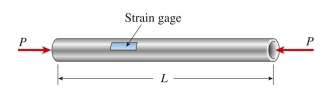
(A) 0.12 mm
(B) 0.26 mm
(C) 0.36 mm
(D) 0.52 mm
Strain in the longitudinal direction of 400
. The shortening of the bar is approximately: (A) 0.12 mm
(B) 0.26 mm
(C) 0.36 mm
(D) 0.52 mm
Question
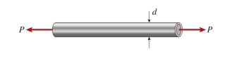
A copper tube with wall thickness of 8 mm must carry an axial tensile force of 175 kN. The allowable tensile stress is 90 MPa. The minimum required outer diameter is approximately: 
Axial deformations
(A) 60 mm
(B) 72 mm
(C) 85 mm
(D) 93 mm
Axial deformations
(A) 60 mm
(B) 72 mm
(C) 85 mm
(D) 93 mm
Question
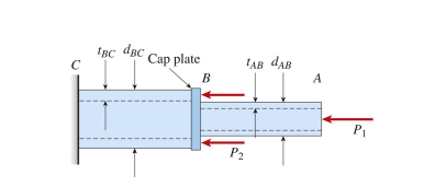
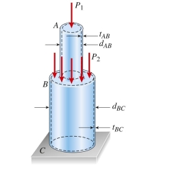
hollow circular post ABC (see figure) supports a load  16 kN acting at the top. A second load
  is uniformly distributed around the cap plate at B. The diameters and thicknesses of the upper and lower parts of the post are
  9 mm, respectively. The lower part of
The post must have the same compressive stress as the upper part. The required magnitude of the load is
is
Approximately: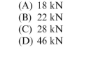
16 kN acting at the top. A second load is uniformly distributed around the cap plate at B. The diameters and thicknesses of the upper and lower parts of the post are 9 mm, respectively. The lower part ofThe post must have the same compressive stress as the upper part. The required magnitude of the load
isApproximately:
Question
steel wire hangs from a high-altitude balloon. The steel has unit weight of 77 kN/m  and yield stress of 280 MPa. The required factor of safety against yield is 2.0. The maximum permissible length of the wire is
Approximately:
(A) 1800 m
(B) 2200 m
(C) 2600 m
(D) 3000 m
and yield stress of 280 MPa. The required factor of safety against yield is 2.0. The maximum permissible length of the wire isApproximately:
(A) 1800 m
(B) 2200 m
(C) 2600 m
(D) 3000 m
Question
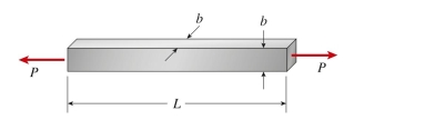
titanium bar (  subjected to tensile load P 5 900 kN. The increase in volume of the bar is approximately:
subjected to tensile load P 5 900 kN. The increase in volume of the bar is approximately: Question
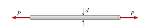
aluminum bar ( 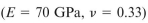 0.33) of diameter 20 mm is stretched by axial forces P, causing its diameter to decrease by 0.022 mm. The load P is approximately:
0.33) of diameter 20 mm is stretched by axial forces P, causing its diameter to decrease by 0.022 mm. The load P is approximately: 
Unlock Deck
Sign up to unlock the cards in this deck!
Unlock Deck
Unlock Deck
1/12
Play
Full screen (f)
Deck 7: Tension, Compression and Shear
1
An elastomeric bearing pad is subjected to a shear force V during a static loading test. The pad has dimensions a 5 150 mm and b 5 225 mm, and thickness t 5 55 mm. The lateral displacement of the top plate with respect to the
Bottom plate is 14 mm under a load P 5 16 kN. The shear modulus of elasticity G of the elastomer is approximately:
Bottom plate is 14 mm under a load P 5 16 kN. The shear modulus of elasticity G of the elastomer is approximately:
D
2
D
3
steel plate weighing 27 kN is hoisted by a cable sling that has a clevis at each end. The pins through the clevises are 22 mm in diameter. Each half of the cable is at an angle of 35° to the vertical. The average shear stress in each pin is approximately:
stress in each pin is approximately: A
4
aluminum bar ( 0.33) of diameter 50 mm cannot exceed a diameter of 50.1 mm when compressed by axial force P. The maximum acceptable compressive load P is approximately:
(A) 190 kN
(B) 200 kN
(C) 470 kN
(D) 860 kN
0.33) of diameter 50 mm cannot exceed a diameter of 50.1 mm when compressed by axial force P. The maximum acceptable compressive load P is approximately:(A) 190 kN
(B) 200 kN
(C) 470 kN
(D) 860 kN
Unlock Deck
Unlock for access to all 12 flashcards in this deck.
Unlock Deck
k this deck
5
polyethylene bar ( 0.4) of diameter 80 mm is inserted in a steel tube of inside diameter 80.2 mm and then compressed by axial force P. The gap between steel tube and polyethylene bar will close when compressive load P is approximately:
(A) 18 kN
(B) 25 kN
(C) 44 kN
(D) 60 kN
0.4) of diameter 80 mm is inserted in a steel tube of inside diameter 80.2 mm and then compressed by axial force P. The gap between steel tube and polyethylene bar will close when compressive load P is approximately:(A) 18 kN
(B) 25 kN
(C) 44 kN
(D) 60 kN
Unlock Deck
Unlock for access to all 12 flashcards in this deck.
Unlock Deck
k this deck
6
Two flanged shafts are connected by eight 18-mm bolts. The diameter of the bolt circle is 240 mm. The allowable shear stress in the bolts is 90 MPa. Ignore friction between the flange plates. The maximum value of torque is approximately:
(A) 19 kN ∙ m
(B) 22 kN ∙ m
(C) 29 kN ∙ m
(D) 37 kN ∙ m T0
T0
torque is approximately:(A) 19 kN ∙ m
(B) 22 kN ∙ m
(C) 29 kN ∙ m
(D) 37 kN ∙ m T0
T0
Unlock Deck
Unlock for access to all 12 flashcards in this deck.
Unlock Deck
k this deck
7
circular aluminum tube of length L = 650 mm is loaded in compression by forces P. The outside and inside diameters are 80 mm and 68 mm, respectively. A strain gage on the outside of the bar records a normal
Strain in the longitudinal direction of 400 . The shortening of the bar is approximately:
(A) 0.12 mm
(B) 0.26 mm
(C) 0.36 mm
(D) 0.52 mm
Strain in the longitudinal direction of 400
. The shortening of the bar is approximately: (A) 0.12 mm
(B) 0.26 mm
(C) 0.36 mm
(D) 0.52 mm
Unlock Deck
Unlock for access to all 12 flashcards in this deck.
Unlock Deck
k this deck
8
A copper tube with wall thickness of 8 mm must carry an axial tensile force of 175 kN. The allowable tensile stress is 90 MPa. The minimum required outer diameter is approximately:
Axial deformations
(A) 60 mm
(B) 72 mm
(C) 85 mm
(D) 93 mm
Axial deformations
(A) 60 mm
(B) 72 mm
(C) 85 mm
(D) 93 mm
Unlock Deck
Unlock for access to all 12 flashcards in this deck.
Unlock Deck
k this deck
9
hollow circular post ABC (see figure) supports a load 16 kN acting at the top. A second load is uniformly distributed around the cap plate at B. The diameters and thicknesses of the upper and lower parts of the post are 9 mm, respectively. The lower part of
The post must have the same compressive stress as the upper part. The required magnitude of the load is
Approximately:
16 kN acting at the top. A second load is uniformly distributed around the cap plate at B. The diameters and thicknesses of the upper and lower parts of the post are 9 mm, respectively. The lower part ofThe post must have the same compressive stress as the upper part. The required magnitude of the load
isApproximately:
Unlock Deck
Unlock for access to all 12 flashcards in this deck.
Unlock Deck
k this deck
10
steel wire hangs from a high-altitude balloon. The steel has unit weight of 77 kN/m and yield stress of 280 MPa. The required factor of safety against yield is 2.0. The maximum permissible length of the wire is
Approximately:
(A) 1800 m
(B) 2200 m
(C) 2600 m
(D) 3000 m
and yield stress of 280 MPa. The required factor of safety against yield is 2.0. The maximum permissible length of the wire isApproximately:
(A) 1800 m
(B) 2200 m
(C) 2600 m
(D) 3000 m
Unlock Deck
Unlock for access to all 12 flashcards in this deck.
Unlock Deck
k this deck
11
titanium bar ( subjected to tensile load P 5 900 kN. The increase in volume of the bar is approximately:
subjected to tensile load P 5 900 kN. The increase in volume of the bar is approximately: Unlock Deck
Unlock for access to all 12 flashcards in this deck.
Unlock Deck
k this deck
12
aluminum bar ( 0.33) of diameter 20 mm is stretched by axial forces P, causing its diameter to decrease by 0.022 mm. The load P is approximately:
0.33) of diameter 20 mm is stretched by axial forces P, causing its diameter to decrease by 0.022 mm. The load P is approximately: Unlock Deck
Unlock for access to all 12 flashcards in this deck.
Unlock Deck
k this deck
Unlock Deck
Unlock for access to all 12 flashcards in this deck.


