Basic Engineering Circuit Analysis 11th Edition by David Irwin ,Robert Nelms
Edition 11ISBN: 978-1118539293Basic Engineering Circuit Analysis 11th Edition by David Irwin ,Robert Nelms
Edition 11ISBN: 978-1118539293 Exercise 43
The load in the diagram in Fig. P9.82 may be modeled by two elements connected in parallel-either a resistor and an inductor or a resistor and a capacitor. Determine which model is appropriate for this load and determine values for R and either L or C if f = 60 Hz and the source supplies 12 kW at a pf = 0.8 leading.
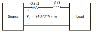
Figure P9.82
Figure P9.82
Explanation Verified
Refer to Figure P9.82 in the textbook.
U...
Basic Engineering Circuit Analysis 11th Edition by David Irwin ,Robert Nelms
Why don’t you like this exercise?
Other Minimum 8 character and maximum 255 character
Character 255


