Exam 10: Magnetism and Electromagnetism
Exam 1: Quantities and Units28 Questions
Exam 2: Voltage, Current, and Resistance69 Questions
Exam 3: Ohms Law67 Questions
Exam 4: Energy and Power63 Questions
Exam 5: Series Circuits64 Questions
Exam 6: Parallel Circuits72 Questions
Exam 7: Series-Parallel Circuits66 Questions
Exam 8: Circuit Theorems and Conversions67 Questions
Exam 9: Branch, Loop, and Node Analyses66 Questions
Exam 10: Magnetism and Electromagnetism65 Questions
Exam 11: Introduction to Alternating Current and Voltage64 Questions
Exam 12: Capacitors65 Questions
Exam 13: Inductors69 Questions
Exam 14: Transformers67 Questions
Exam 15: RC Circuits66 Questions
Exam 16: RL Circuits98 Questions
Exam 17: RlC Circuits and Resonance98 Questions
Exam 18: Passive Filters58 Questions
Exam 19: Circuit Theorems in Ac Analysis60 Questions
Exam 20: Time Response of Reactive Circuits45 Questions
Exam 21: Three-Phase Systems in Power Applications35 Questions
Select questions type
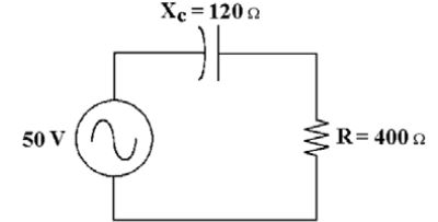 -If the frequency increases in Figure 10-1, the phase angle ________ and the impedance ________.
Free
(Multiple Choice)
4.8/5  (29)
(29)
Correct Answer: Verified
A
The phasor combination of V  in an RC series circuit equals the source voltage.
Free
(True/False)
4.9/5 (37)
Correct Answer:Verified
True
-What is the circuitʹs impedance in Figure 10-1?
Free
(Multiple Choice)
4.8/5 (40)
Correct Answer:Verified
B
It has been determined that the phase shift of a given parallel RC circuit is lower than predicted. Which of the following most likely has caused this?
(Multiple Choice)
4.8/5 (40)
When the frequency applied to an RC circuit varies, the value of  varies.
(True/False)
4.7/5 (28)
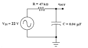 -If the input voltage increases to 50 V in Figure 10-3, what is the output voltage at the cutoff frequency?
(Multiple Choice)
4.8/5 (33)
-If the circuit in Figure 10-3 has an output voltage thatʹs too high at the cutoff frequency, ________.
(Multiple Choice)
4.8/5 (29)
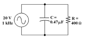 -What change would increase the power factor in Figure 10-2?
(Multiple Choice)
4.8/5 (31)
An RC circuit can be used as a filter to eliminate selected frequencies.
(True/False)
4.8/5 (41)
-If the operating frequency increases in Figure 10-1, how does the phase angle change?
(Multiple Choice)
4.8/5 (27)
If the true power is 100 W and the reactive power is 100 VAR, the apparent power is ________.
(Multiple Choice)
4.9/5 (32)
-If the source voltage is changed to 100 V in Figure 10-1, find the true power.
(Multiple Choice)
4.7/5 (40)
-If the resistance is reduced to  in Figure 10-3, the cutoff frequency equals ________.
(Multiple Choice)
4.8/5 (26)
-If the resistor value increases in Figure 10-2, then how does the total current change?
(Multiple Choice)
4.9/5 (37)
-If the frequency decreases in Figure 10-1, the phase angle ________ and the impedance ________.
(Multiple Choice)
4.9/5 (30)
The phase angle of an RC circuit varies inversely with frequency.
(True/False)
4.9/5 (27)
As the frequency applied to an RC circuit increases, the impedance decreases.
(True/False)
4.7/5 (39)
If there is  across the resistor and
  across the capacitor in a series RC circuit, then the source voltage equals ________.
(Multiple Choice)
4.8/5 (26)
-What change would decrease the power factor in Figure 10-2?
(Multiple Choice)
4.9/5 (30)
Filters
- Essay(0)
- Multiple Choice(0)
- Short Answer(0)
- True False(0)
- Matching(0)