Deck 23: Circuits
Full screen (f)
Question
Question
Question
A 5-µF, a 7-µF, and an unknown capacitor CX are connected in parallel between points a and b as shown in the figure. What do you know about the equivalent capacitance Cab between a and b? (There could be more than one correct choice.) 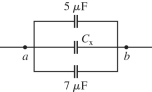
A) Cab > 12 µF
B) Cab > CX
C) 5 µF < Cab < 12 µF
D) Cab < 5 µF
E) Cab < CX
A) Cab > 12 µF
B) Cab > CX
C) 5 µF < Cab < 12 µF
D) Cab < 5 µF
E) Cab < CX
Question
Question
Question
Question
Question
Question
Question
Question
Question
Question
Question
Draw a circuit consisting of a battery connected to two resistors, R1 and R2, in series with each other and a capacitor C connected across the resistors. 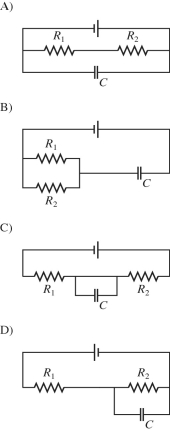
Question
Draw a circuit with two batteries, a resistor between them, and a capacitor in parallel with the resistor. The batteries are connected negative pole to positive pole. 
Question
Question
Draw a circuit with a battery connected to four resistors, R1, R2, R3, and R4, as follows. Resistors R1 and R2 are connected in parallel with each other, resistors R3 and R4 are connected in parallel with each other, and both parallel sets of resistors are connected in series with each other across the battery. 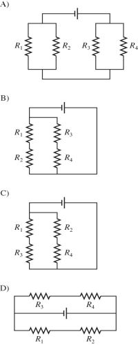
Question
A 9-V battery is hooked up to two resistors in series using wires of negligible resistance. One has a resistance of 5 Ω, and the other has a resistance of 10 Ω. Several locations along the circuit are marked with letters, as shown in the figure. Which statements about this circuit are true? (There could be more than one correct choice.) 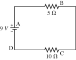
A) The current is exactly the same at points A, B, C, and D.
B) The current at A is greater than the current at B, which is equal to the current at C, which is greater than the current at D.
C) The current at A is greater than the current at B, which is greater than the current at C, which is greater than the current at D.
D) The potential at B is equal to the potential at C.
E) The potential at D is equal to the potential at C.
Question
Question
Question
A charged capacitor is connected in series with a resistor and an open switch. At time t = 0 s, the switch is closed. Which of the graphs below best describes the potential difference V across the capacitor as a function of time t? 
Question
A charged capacitor is connected in series with a resistor and an open switch. At time t = 0 s, the switch is closed. Which of the graphs below best describes the potential difference V across the resistor as a function of time t? 
Question
Question
Identical light bulbs can be attached to identical ideal batteries in three different ways (A, B, orC), as shown in the figure. The ranking (from lowest to highest) of the total power produced by the battery is
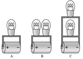
A) B, A, C
B) A, B, C
C) C, B, A
D) A, C, B
A) B, A, C
B) A, B, C
C) C, B, A
D) A, C, B
Question
For the circuit shown in the figure, write the Kirchhoff loop equation for the entire outside loop. Notice the directions of the currents! 
Question
A charged capacitor is connected in series with a resistor and an open switch. At time t = 0 s, the switch is closed. Which of the graphs below best describes the current I through the resistor as a function of time t? 
Question
In the circuit shown in the figure, the resistor R has a variable resistance. As R is decreased, what happens to the currents? 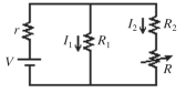
A) I1 remains unchanged and I2 increases.
B) I1 decreases and I2 decreases.
C) I1 decreases and I2 increases.
D) I1 increases and I2 decreases.
E) I1 increases and I2 increases.
A) I1 remains unchanged and I2 increases.
B) I1 decreases and I2 decreases.
C) I1 decreases and I2 increases.
D) I1 increases and I2 decreases.
E) I1 increases and I2 increases.
Question
Question
Question
An uncharged capacitor is connected in series with a resistor, a dc battery, and an open switch. At time t = 0 s, the switch is closed. Which of the graphs below best describes the potential difference V across the resistor as a function of time t? 
Question
Question
Question
Identical ideal batteries are connected in different arrangements to the same light bulb, as shown in the figure. For which arrangement will the bulb shine the brightest? 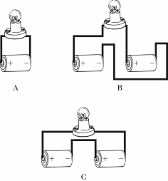
A) A
B) B
C) C
A) A
B) B
C) C
Question
Question
An uncharged capacitor is connected in series with a resistor, a dc battery, and an open switch. At time t = 0 s, the switch is closed. Which of the graphs below best describes the charge Q on the capacitor as a function of time t? 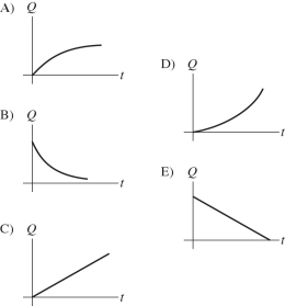
Question
A 9-V battery is hooked up to two resistors in series. One has a resistance of 5 Ω, and the other has a resistance of 10 Ω. Several locations along the circuit are marked with letters, as shown in the figure. Through which resistor is energy being dissipated at the higher rate? 
A) the 10-Ω resistor
B) the 5-Ω resistor
C) Energy is being dissipated by both resistors at the same rate.
A) the 10-Ω resistor
B) the 5-Ω resistor
C) Energy is being dissipated by both resistors at the same rate.
Question
For the circuit shown in the figure, write the Kirchhoff current equation for the node labeled A. Notice the directions of the currents! 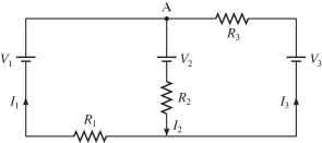
Question
A charged capacitor is connected in series with a resistor and an open switch. At time t = 0 s, the switch is closed. Which of the graphs below best describes the charge Q on the capacitor as a function of time t? 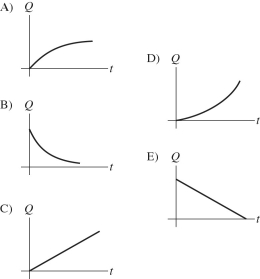
Question
An uncharged capacitor is connected in series with a resistor, a dc battery, and an open switch. At time t = 0 s, the switch is closed. Which of the graphs below best describes the current I through the resistor as a function of time t? 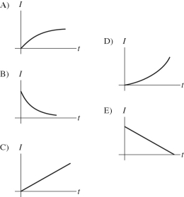
Question
Question
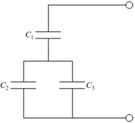
A system of four capacitors is connected across a 90-V voltage source as shown in the figure. What is the equivalent capacitance of this system? 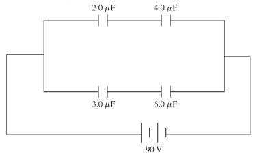
A) 1.5 μF
B) 15 μF
C) 3.6 μF
D) 3.3 μF
A) 1.5 μF
B) 15 μF
C) 3.6 μF
D) 3.3 μF
Question
Question
A network of capacitors is mostly inside a sealed box, but one capacitor CX is sticking out, as shown in the figure. When you connect a multimeter across points a and b, it reads 27.0 µF. What is CX? 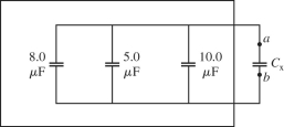
A) 27.0 µF
B) 23.0 µF
C) 4.0 µF
D) 2.4 µF
E) 2.2 µF
A) 27.0 µF
B) 23.0 µF
C) 4.0 µF
D) 2.4 µF
E) 2.2 µF
Question
A potential difference of V = 100 V is applied across two capacitors in series, as shown in the figure. If  =
=  and the voltage drop across it is 75 V, what is the capacitance of C2?
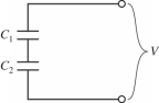
A) 30 μF
B) 2.5 μF
C) 7.5 μF
D) 3.3 μF
= and the voltage drop across it is 75 V, what is the capacitance of C2? A) 30 μF
B) 2.5 μF
C) 7.5 μF
D) 3.3 μF
Question
Two capacitors are connected as shown in the figure, with C1 = 4.0 µF and C2 = 7.0 µF. If a voltage source V = 90 V is applied across the combination, find the potential difference across C1. 
A) 57 V
B) 36 V
C) 60 V
D) 9.0 V
A) 57 V
B) 36 V
C) 60 V
D) 9.0 V
Question
An uncharged capacitor is connected in series with a resistor, a dc battery, and an open switch. At time t = 0 s, the switch is closed. Which of the graphs below best describes the potential difference V across the capacitor as a function of time t? 
Question
Three capacitors of equal capacitance are arranged as shown in the figure, with a voltage source across the combination. If the voltage drop across C1 is  what is the voltage drop across
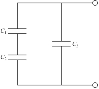
A) 20 V
B) 10.0 V
C) 40 V
D) 30 V
what is the voltage drop across A) 20 V
B) 10.0 V
C) 40 V
D) 30 V
Question
A 5.0-μF and a 12.0-μF capacitor are connected in series, and the series arrangement is connected in parallel to a  capacitor. How much capacitance would a single capacitor need to replace this combination of three capacitors?
A) 33 μF
B) 13 μF
C) 16 μF
D) 38 μF
capacitor. How much capacitance would a single capacitor need to replace this combination of three capacitors?A) 33 μF
B) 13 μF
C) 16 μF
D) 38 μF
Question
Question
Question
Question
Three capacitors are connected as shown in the figure. What is the equivalent capacitance between points A and B? 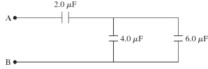
A) 12 μF
B) 4.0 μC
C) 7.1 μF
D) 1.7 μF
E) 8.0 μF
A) 12 μF
B) 4.0 μC
C) 7.1 μF
D) 1.7 μF
E) 8.0 μF
Question
A system of four capacitors is connected across a 90-V voltage source as shown in the figure.
(a) What is the potential difference across the plates of the 6.0-µF capacitor?
(b) What is the charge on the 3.0-µF capacitor?
(a) What is the potential difference across the plates of the 6.0-µF capacitor?
(b) What is the charge on the 3.0-µF capacitor?
Question
Question
Question
A system of four capacitors is connected across a 90-V voltage source as shown in the figure.
(a) What is the charge on the 4.0-µF capacitor?
(b) What is the charge on the 2.0-µF capacitor?
(a) What is the charge on the 4.0-µF capacitor?
(b) What is the charge on the 2.0-µF capacitor?
Question
A network of capacitors is connected across a potential difference V0 as shown in the figure.
(a) What should V0 be so that the 60.0-µF capacitor will have 18.0 µC of charge on each of its plates?
(b) Under the conditions of part (a), how much total energy is stored in this network of capacitors?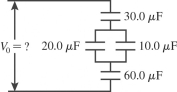
(a) What should V0 be so that the 60.0-µF capacitor will have 18.0 µC of charge on each of its plates?
(b) Under the conditions of part (a), how much total energy is stored in this network of capacitors?
Question
Question
Question
A 5.0-μF, a 14-μF, and a  capacitor are connected in parallel. How much capacitance would a single capacitor need to have to replace the three capacitors?
A) 40 μF
B)
C) 5.0 μF
D) 14 μF
capacitor are connected in parallel. How much capacitance would a single capacitor need to have to replace the three capacitors?A) 40 μF
B)
C) 5.0 μF
D) 14 μF
Question
What is the equivalent resistance between points A and B of the network shown in the figure? 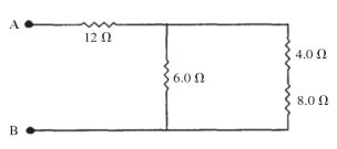
Question
Question
Question
The network shown is assembled with uncharged capacitors X , Y, and Z, with 
 and
and  The switches S1 and S2 are initially open, and a potential difference Vab = 120 V is applied between points a and b. After the network is assembled, switch S1 is then closed, but switch S2 is kept open. What is the final potential difference across capacitor Z?
A) 100 V
B) 600 V
C) 55 V
D) 38 V
E) 29 V
and The switches S1 and S2 are initially open, and a potential difference Vab = 120 V is applied between points a and b. After the network is assembled, switch S1 is then closed, but switch S2 is kept open. What is the final potential difference across capacitor Z? A) 100 V
B) 600 V
C) 55 V
D) 38 V
E) 29 V
Question
Question
Question
Question
Three 2.0-Ω resistors are connected to form the sides of an equilateral triangle ABC as shown in the figure. What is the equivalent resistance between any two points, AB, BC, or AC, of this circuit? 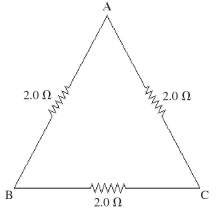
A) 2.0 Ω
B) 6.0 Ω
C) 4.3 Ω
D) 3.3 Ω
E) 1.3 Ω
A) 2.0 Ω
B) 6.0 Ω
C) 4.3 Ω
D) 3.3 Ω
E) 1.3 Ω
Question
The capacitive network shown in the figure is assembled with initially uncharged capacitors. Assume that all the quantities in the figure are accurate to two significant figures. The switch S in the network is kept open throughout. What is the total energy stored in the seven capacitors? 
A) 48 mJ
B) 72 mJ
C) 96 mJ
D) 120 mJ
E) 144 mJ
A) 48 mJ
B) 72 mJ
C) 96 mJ
D) 120 mJ
E) 144 mJ
Question
The network shown is assembled with uncharged capacitors X , Y, and Z, with 
 and
and  The switches S1 and S2 are initially open, and a potential difference Vab = 120 V is applied between points a and b. After the network is assembled, switch S1 is then closed, but switch S2 is kept open. How much charge is finally stored in capacitor Y?
A) 110 µC
B) 54 µC
C) 81 µC
D) 140 µC
E) 160 µC
and The switches S1 and S2 are initially open, and a potential difference Vab = 120 V is applied between points a and b. After the network is assembled, switch S1 is then closed, but switch S2 is kept open. How much charge is finally stored in capacitor Y? A) 110 µC
B) 54 µC
C) 81 µC
D) 140 µC
E) 160 µC
Question
The network shown is assembled with uncharged capacitors X , Y, and Z, with CX = 4.0 μF, CY = 6.0 μF, and CZ = 5.0 μF. The switches S1 and S2 are initially open, and a potential difference Vab = 120 V is applied between points a and b. After the network is assembled, switch S1 is then closed, but switch S2 is kept open. What is the final potential difference across capacitor X? 
A) 120 V
B) 82 V
C) 75 V
D) 67 V
E) 60 V
A) 120 V
B) 82 V
C) 75 V
D) 67 V
E) 60 V
Question
Question
Five 2.0-Ω resistors are connected as shown in the figure. What is the equivalent resistance of this combination between points a and b? 
A) 1.0 Ω
B) 10.0 Ω
C) 2.0 Ω
D) 6.0 Ω
E) 0.40 Ω
A) 1.0 Ω
B) 10.0 Ω
C) 2.0 Ω
D) 6.0 Ω
E) 0.40 Ω
Question
Question
The resistors in the circuit shown in the figure each have a resistance of  What is the equivalent resistance between points a and b of this combination?
A) 700 Ω
B) 2800 Ω
C) 175 Ω
D) 1400 Ω
What is the equivalent resistance between points a and b of this combination? A) 700 Ω
B) 2800 Ω
C) 175 Ω
D) 1400 Ω
Question
Question
What is the equivalent resistance in the circuit shown in the figure? 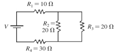
A) 80 Ω
B) 55 Ω
C) 50 Ω
D) 35 Ω
A) 80 Ω
B) 55 Ω
C) 50 Ω
D) 35 Ω
Question
Three capacitors are arranged as shown in the figure, with a voltage source connected across the combination. C1 has a capacitance of 
 has a capacitance of
  and
and  has a capacitance of
  Find the potential drop across the entire arrangement if the potential drop across C2 is
A) 1500 V
B) 1000 V
C) 470 V
D) 430 V
has a capacitance of and has a capacitance of Find the potential drop across the entire arrangement if the potential drop across C2 is A) 1500 V
B) 1000 V
C) 470 V
D) 430 V
Question
The network shown is assembled with uncharged capacitors X , Y, and Z, with 
 and
and  The switches S1 and S2 are initially open, and a potential difference Vab = 120 V is applied between points a and b. After the network is assembled, switch S1 is then closed, but switch S2 is kept open. How much energy is finally stored in capacitor X?
A) 29 mJ
B) 0.48 mJ
C) 0.24 mJ
D) 58 mJ
E) 0.96 mJ
and The switches S1 and S2 are initially open, and a potential difference Vab = 120 V is applied between points a and b. After the network is assembled, switch S1 is then closed, but switch S2 is kept open. How much energy is finally stored in capacitor X? A) 29 mJ
B) 0.48 mJ
C) 0.24 mJ
D) 58 mJ
E) 0.96 mJ
Question
Each of the resistors shown in the figure has a resistance of  What is the equivalent resistance between points a and b of this combination?
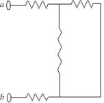
A) 450.0 Ω
B) 720.0 Ω
C) 540.0 Ω
D) 180.0 Ω
What is the equivalent resistance between points a and b of this combination? A) 450.0 Ω
B) 720.0 Ω
C) 540.0 Ω
D) 180.0 Ω

Unlock Deck
Sign up to unlock the cards in this deck!
Unlock Deck
Unlock Deck
1/157
Play
Full screen (f)
Deck 23: Circuits
1
When two or more different capacitors are connected in series across a potential source, which of the following statements must be true? (There could be more than one correct choice.)
A) The total voltage across the combination is the algebraic sum of the voltages across the individual capacitors.
B) Each capacitor carries the same amount of charge.
C) The equivalent capacitance of the combination is less than the capacitance of any of the capacitors.
D) The potential difference across each capacitor is the same.
E) The capacitor with the largest capacitance has the most charge.
A, B, C
2
Three identical capacitors are connected in series across a potential source (battery). If a charge of Q flows into this combination of capacitors, how much charge does each capacitor carry?
A) 3Q
B) Q
C) Q/3
D) Q/9
A) 3Q
B) Q
C) Q/3
D) Q/9
B
3
A 5-µF, a 7-µF, and an unknown capacitor CX are connected in parallel between points a and b as shown in the figure. What do you know about the equivalent capacitance Cab between a and b? (There could be more than one correct choice.)
A) Cab > 12 µF
B) Cab > CX
C) 5 µF < Cab < 12 µF
D) Cab < 5 µF
E) Cab < CX
A) Cab > 12 µF
B) Cab > CX
C) 5 µF < Cab < 12 µF
D) Cab < 5 µF
E) Cab < CX
A, B
4
As more resistors are added in parallel across a constant voltage source, the power supplied by the source
A) increases.
B) decreases.
C) does not change.
D) increases for a time and then starts to decrease.
A) increases.
B) decreases.
C) does not change.
D) increases for a time and then starts to decrease.
Unlock Deck
Unlock for access to all 157 flashcards in this deck.
Unlock Deck
k this deck
5
Four unequal resistors are connected in series with each other. Which one of the following statements is correct about this combination?
A) The equivalent resistance is equal to that of any one of the resistors.
B) The equivalent resistance is equal to average of the four resistances.
C) The equivalent resistance is less than that of the smallest resistor.
D) The equivalent resistance is less than that of the largest resistor.
E) The equivalent resistance is more than the largest resistance.
Unlock Deck
Unlock for access to all 157 flashcards in this deck.
Unlock Deck
k this deck
6
The lamps in a string of decorative lights are connected in parallel across a constant-voltage power source. What happens if one lamp burns out? (Assume negligible resistance in the wires leading to the lamps.)
A) The brightness of the lamps will not change appreciably.
B) The other lamps get brighter equally.
C) The other lamps get brighter, but some get brighter than others.
D) The other lamps get dimmer equally.
E) The other lamps get dimmer, but some get dimmer than others.
A) The brightness of the lamps will not change appreciably.
B) The other lamps get brighter equally.
C) The other lamps get brighter, but some get brighter than others.
D) The other lamps get dimmer equally.
E) The other lamps get dimmer, but some get dimmer than others.
Unlock Deck
Unlock for access to all 157 flashcards in this deck.
Unlock Deck
k this deck
7
A 5-µF, a 7-µF, and an unknown capacitor CX are connected in series between points a and b. What do you know about the equivalent capacitance Cab between a and b? (There could be more than one correct choice.)
A) Cab > 12 µF
B) 5 µF < Cab < 7 µF
C) 5 µF < Cab < 12 µF
D) Cab < 5 µF
E) Cab < CX
A) Cab > 12 µF
B) 5 µF < Cab < 7 µF
C) 5 µF < Cab < 12 µF
D) Cab < 5 µF
E) Cab < CX
Unlock Deck
Unlock for access to all 157 flashcards in this deck.
Unlock Deck
k this deck
8
When two or more different capacitors are connected in parallel across a potential source (battery), which of the following statements must be true? (There could be more than one correct choice.)
A) The potential difference across each capacitor is the same.
B) Each capacitor carries the same amount of charge.
C) The equivalent capacitance of the combination is less than the capacitance of any one of the capacitors.
D) The capacitor with the largest capacitance has the largest potential difference across it.
E) The capacitor with the largest capacitance has the most charge.
Unlock Deck
Unlock for access to all 157 flashcards in this deck.
Unlock Deck
k this deck
9
Three identical capacitors are connected in parallel to a potential source (battery). If a charge of Q flows into this combination, how much charge does each capacitor carry?
A) 3Q
B) Q
C) Q/3
D) Q/9
A) 3Q
B) Q
C) Q/3
D) Q/9
Unlock Deck
Unlock for access to all 157 flashcards in this deck.
Unlock Deck
k this deck
10
Suppose you have two capacitors and want to use them to store the maximum amount of energy by connecting them across a voltage source. You should connect them
A) in series across the source.
B) in parallel across the source.
C) It doesn't matter because the stored energy is the same either way.
A) in series across the source.
B) in parallel across the source.
C) It doesn't matter because the stored energy is the same either way.
Unlock Deck
Unlock for access to all 157 flashcards in this deck.
Unlock Deck
k this deck
11
When different resistors are connected in parallel across an ideal battery, we can be certain that
A) the same current flows in each one.
B) the potential difference across each is the same.
C) the power dissipated in each is the same.
D) their equivalent resistance is greater than the resistance of any one of the individual resistances.
E) their equivalent resistance is equal to the average of the individual resistances.
Unlock Deck
Unlock for access to all 157 flashcards in this deck.
Unlock Deck
k this deck
12
As more resistors are added in series to a constant voltage source, the power supplied by the source
A) increases.
B) decreases.
C) does not change.
D) increases for a time and then starts to decrease.
A) increases.
B) decreases.
C) does not change.
D) increases for a time and then starts to decrease.
Unlock Deck
Unlock for access to all 157 flashcards in this deck.
Unlock Deck
k this deck
13
You obtain a 100-W light bulb and a 50-W light bulb. Instead of connecting them in the normal way, you devise a circuit that places them in series across normal household voltage. If each one is an incandescent bulb of fixed resistance, which statement about these bulbs is correct?
A) Both bulbs glow with the same brightness, but less than their normal brightness.
B) Both bulbs glow with the same brightness, but more than their normal brightness.
C) The 100-W bulb glows brighter than the 50-W bulb.
D) The 50-W bulb glows more brightly than the 100-W bulb.
A) Both bulbs glow with the same brightness, but less than their normal brightness.
B) Both bulbs glow with the same brightness, but more than their normal brightness.
C) The 100-W bulb glows brighter than the 50-W bulb.
D) The 50-W bulb glows more brightly than the 100-W bulb.
Unlock Deck
Unlock for access to all 157 flashcards in this deck.
Unlock Deck
k this deck
14
Draw a circuit consisting of a battery connected to two resistors, R1 and R2, in series with each other and a capacitor C connected across the resistors.
Unlock Deck
Unlock for access to all 157 flashcards in this deck.
Unlock Deck
k this deck
15
Draw a circuit with two batteries, a resistor between them, and a capacitor in parallel with the resistor. The batteries are connected negative pole to positive pole.
Unlock Deck
Unlock for access to all 157 flashcards in this deck.
Unlock Deck
k this deck
16
Four unequal resistors are connected in a parallel with each other. Which one of the following statements is correct about this combination?
A) The equivalent resistance is less than that of the smallest resistor.
B) The equivalent resistance is equal to the average of the four resistances.
C) The equivalent resistance is midway between the largest and smallest resistance.
D) The equivalent resistance is more than the largest resistance.
E) None of the other choices is correct.
Unlock Deck
Unlock for access to all 157 flashcards in this deck.
Unlock Deck
k this deck
17
Draw a circuit with a battery connected to four resistors, R1, R2, R3, and R4, as follows. Resistors R1 and R2 are connected in parallel with each other, resistors R3 and R4 are connected in parallel with each other, and both parallel sets of resistors are connected in series with each other across the battery.
Unlock Deck
Unlock for access to all 157 flashcards in this deck.
Unlock Deck
k this deck
18
A 9-V battery is hooked up to two resistors in series using wires of negligible resistance. One has a resistance of 5 Ω, and the other has a resistance of 10 Ω. Several locations along the circuit are marked with letters, as shown in the figure. Which statements about this circuit are true? (There could be more than one correct choice.)
A) The current is exactly the same at points A, B, C, and D.
B) The current at A is greater than the current at B, which is equal to the current at C, which is greater than the current at D.
C) The current at A is greater than the current at B, which is greater than the current at C, which is greater than the current at D.
D) The potential at B is equal to the potential at C.
E) The potential at D is equal to the potential at C.
Unlock Deck
Unlock for access to all 157 flashcards in this deck.
Unlock Deck
k this deck
19
When unequal resistors are connected in parallel in a circuit,
A) the same current always runs through each resistor.
B) the potential drop is always the same across each resistor.
C) the largest resistance has the largest current through it.
D) the power generated in each resistor is the same.
A) the same current always runs through each resistor.
B) the potential drop is always the same across each resistor.
C) the largest resistance has the largest current through it.
D) the power generated in each resistor is the same.
Unlock Deck
Unlock for access to all 157 flashcards in this deck.
Unlock Deck
k this deck
20
When unequal resistors are connected in series across an ideal battery,
A) the same power is dissipated in each one.
B) the potential difference across each is the same.
C) the current flowing in each is the same.
D) the equivalent resistance of the circuit is less than that of the smallest resistor.
E) the equivalent resistance of the circuit is equal to the average of all the resistances.
Unlock Deck
Unlock for access to all 157 flashcards in this deck.
Unlock Deck
k this deck
21
A charged capacitor is connected in series with a resistor and an open switch. At time t = 0 s, the switch is closed. Which of the graphs below best describes the potential difference V across the capacitor as a function of time t?
Unlock Deck
Unlock for access to all 157 flashcards in this deck.
Unlock Deck
k this deck
22
A charged capacitor is connected in series with a resistor and an open switch. At time t = 0 s, the switch is closed. Which of the graphs below best describes the potential difference V across the resistor as a function of time t?
Unlock Deck
Unlock for access to all 157 flashcards in this deck.
Unlock Deck
k this deck
23
A resistor is made out of a wire having a length L. When the ends of the wire are attached across the terminals of an ideal battery having a constant voltage V0 across its terminals, a current I flows through the wire. If the wire were cut in half, making two wires of length L/2, and both wires were attached across the terminals of the battery (the right ends of both wires attached to one terminal, and the left ends attached to the other terminal), how much current would the battery put out?
A) 4I
B) 2I
C) I
D) I/2
E) I/4
A) 4I
B) 2I
C) I
D) I/2
E) I/4
Unlock Deck
Unlock for access to all 157 flashcards in this deck.
Unlock Deck
k this deck
24
Identical light bulbs can be attached to identical ideal batteries in three different ways (A, B, orC), as shown in the figure. The ranking (from lowest to highest) of the total power produced by the battery is
A) B, A, C
B) A, B, C
C) C, B, A
D) A, C, B
A) B, A, C
B) A, B, C
C) C, B, A
D) A, C, B
Unlock Deck
Unlock for access to all 157 flashcards in this deck.
Unlock Deck
k this deck
25
For the circuit shown in the figure, write the Kirchhoff loop equation for the entire outside loop. Notice the directions of the currents!
Unlock Deck
Unlock for access to all 157 flashcards in this deck.
Unlock Deck
k this deck
26
A charged capacitor is connected in series with a resistor and an open switch. At time t = 0 s, the switch is closed. Which of the graphs below best describes the current I through the resistor as a function of time t?
Unlock Deck
Unlock for access to all 157 flashcards in this deck.
Unlock Deck
k this deck
27
In the circuit shown in the figure, the resistor R has a variable resistance. As R is decreased, what happens to the currents?
A) I1 remains unchanged and I2 increases.
B) I1 decreases and I2 decreases.
C) I1 decreases and I2 increases.
D) I1 increases and I2 decreases.
E) I1 increases and I2 increases.
A) I1 remains unchanged and I2 increases.
B) I1 decreases and I2 decreases.
C) I1 decreases and I2 increases.
D) I1 increases and I2 decreases.
E) I1 increases and I2 increases.
Unlock Deck
Unlock for access to all 157 flashcards in this deck.
Unlock Deck
k this deck
28
Kirchhoff's junction rule is a statement of
A) the law of conservation of momentum.
B) the law of conservation of charge.
C) the law of conservation of energy.
D) the law of conservation of angular momentum.
E) Newton's second law.
A) the law of conservation of momentum.
B) the law of conservation of charge.
C) the law of conservation of energy.
D) the law of conservation of angular momentum.
E) Newton's second law.
Unlock Deck
Unlock for access to all 157 flashcards in this deck.
Unlock Deck
k this deck
29
A capacitor C is connected in series with a resistor R across a battery and an open switch. If a second capacitor of capacitance 2C is connected in parallel with the first one, the time constant of the new RC circuit will be
A) the same as before.
B) twice as large as before.
C) three times a large as before.
D) one-half as large as before.
E) one-fourth as large as before.
A) the same as before.
B) twice as large as before.
C) three times a large as before.
D) one-half as large as before.
E) one-fourth as large as before.
Unlock Deck
Unlock for access to all 157 flashcards in this deck.
Unlock Deck
k this deck
30
An uncharged capacitor is connected in series with a resistor, a dc battery, and an open switch. At time t = 0 s, the switch is closed. Which of the graphs below best describes the potential difference V across the resistor as a function of time t?
Unlock Deck
Unlock for access to all 157 flashcards in this deck.
Unlock Deck
k this deck
31
A resistor, an uncharged capacitor, a dc voltage source, and an open switch are all connected in series. The switch is closed at time t = 0 s. Which one of the following is a correct statement about the circuit?
A) The capacitor charges to its maximum value in one time constant.
B) The capacitor charges to its maximum value in two time constants.
C) The potential difference across the resistor is always equal to the potential difference across the capacitor.
D) Current flows through the circuit even after the capacitor is essentially fully charged.
E) Once the capacitor is essentially fully charged, there is no current in the circuit.
Unlock Deck
Unlock for access to all 157 flashcards in this deck.
Unlock Deck
k this deck
32
A resistor, an uncharged capacitor, a dc voltage source, and an open switch are all connected in series. The switch is closed at time t = 0 s. Which one of the following is a correct statement about this circuit?
A) The charge on the capacitor after four time constants is about 98% of the maximum value.
B) The charge on the capacitor after one time constant is 50% of its maximum value.
C) The charge on the capacitor after one time constant is 1/e of its maximum value.
D) The voltage on the capacitor after one time constant is 1/e of the maximum value.
E) The voltage on this capacitor after one time constant is 100% of its maximum value.
Unlock Deck
Unlock for access to all 157 flashcards in this deck.
Unlock Deck
k this deck
33
Identical ideal batteries are connected in different arrangements to the same light bulb, as shown in the figure. For which arrangement will the bulb shine the brightest?
A) A
B) B
C) C
A) A
B) B
C) C
Unlock Deck
Unlock for access to all 157 flashcards in this deck.
Unlock Deck
k this deck
34
Kirchhoff's loop rule is a statement of
A) the law of conservation of momentum.
B) the law of conservation of charge.
C) the law of conservation of energy.
D) the law of conservation of angular momentum.
E) Newton's second law.
A) the law of conservation of momentum.
B) the law of conservation of charge.
C) the law of conservation of energy.
D) the law of conservation of angular momentum.
E) Newton's second law.
Unlock Deck
Unlock for access to all 157 flashcards in this deck.
Unlock Deck
k this deck
35
An uncharged capacitor is connected in series with a resistor, a dc battery, and an open switch. At time t = 0 s, the switch is closed. Which of the graphs below best describes the charge Q on the capacitor as a function of time t?
Unlock Deck
Unlock for access to all 157 flashcards in this deck.
Unlock Deck
k this deck
36
A 9-V battery is hooked up to two resistors in series. One has a resistance of 5 Ω, and the other has a resistance of 10 Ω. Several locations along the circuit are marked with letters, as shown in the figure. Through which resistor is energy being dissipated at the higher rate?
A) the 10-Ω resistor
B) the 5-Ω resistor
C) Energy is being dissipated by both resistors at the same rate.
A) the 10-Ω resistor
B) the 5-Ω resistor
C) Energy is being dissipated by both resistors at the same rate.
Unlock Deck
Unlock for access to all 157 flashcards in this deck.
Unlock Deck
k this deck
37
For the circuit shown in the figure, write the Kirchhoff current equation for the node labeled A. Notice the directions of the currents!
Unlock Deck
Unlock for access to all 157 flashcards in this deck.
Unlock Deck
k this deck
38
A charged capacitor is connected in series with a resistor and an open switch. At time t = 0 s, the switch is closed. Which of the graphs below best describes the charge Q on the capacitor as a function of time t?
Unlock Deck
Unlock for access to all 157 flashcards in this deck.
Unlock Deck
k this deck
39
An uncharged capacitor is connected in series with a resistor, a dc battery, and an open switch. At time t = 0 s, the switch is closed. Which of the graphs below best describes the current I through the resistor as a function of time t?
Unlock Deck
Unlock for access to all 157 flashcards in this deck.
Unlock Deck
k this deck
40
A capacitor C is connected in series with a resistor R across a battery and an open switch. If a second capacitor of capacitance 2C is connected in series with the first one, the time constant of the new RC circuit will be
A) the same as before.
B) larger than before.
C) smaller than before.
D) variable.
A) the same as before.
B) larger than before.
C) smaller than before.
D) variable.
Unlock Deck
Unlock for access to all 157 flashcards in this deck.
Unlock Deck
k this deck
41
A system of four capacitors is connected across a 90-V voltage source as shown in the figure. What is the equivalent capacitance of this system?
A) 1.5 μF
B) 15 μF
C) 3.6 μF
D) 3.3 μF
A) 1.5 μF
B) 15 μF
C) 3.6 μF
D) 3.3 μF
Unlock Deck
Unlock for access to all 157 flashcards in this deck.
Unlock Deck
k this deck
42
A 5.0-μF capacitor and a 7.0-μF capacitor are connected in series across an 8.0-V potential source. What is the potential difference across the 5.0-μF capacitor?
A) 0 V
B) 8.0 V
C) 2.7 V
D) 3.6 V
E) 4.7 V
A) 0 V
B) 8.0 V
C) 2.7 V
D) 3.6 V
E) 4.7 V
Unlock Deck
Unlock for access to all 157 flashcards in this deck.
Unlock Deck
k this deck
43
A network of capacitors is mostly inside a sealed box, but one capacitor CX is sticking out, as shown in the figure. When you connect a multimeter across points a and b, it reads 27.0 µF. What is CX?
A) 27.0 µF
B) 23.0 µF
C) 4.0 µF
D) 2.4 µF
E) 2.2 µF
A) 27.0 µF
B) 23.0 µF
C) 4.0 µF
D) 2.4 µF
E) 2.2 µF
Unlock Deck
Unlock for access to all 157 flashcards in this deck.
Unlock Deck
k this deck
44
A potential difference of V = 100 V is applied across two capacitors in series, as shown in the figure. If = and the voltage drop across it is 75 V, what is the capacitance of C2?
A) 30 μF
B) 2.5 μF
C) 7.5 μF
D) 3.3 μF
= and the voltage drop across it is 75 V, what is the capacitance of C2? A) 30 μF
B) 2.5 μF
C) 7.5 μF
D) 3.3 μF
Unlock Deck
Unlock for access to all 157 flashcards in this deck.
Unlock Deck
k this deck
45
Two capacitors are connected as shown in the figure, with C1 = 4.0 µF and C2 = 7.0 µF. If a voltage source V = 90 V is applied across the combination, find the potential difference across C1.
A) 57 V
B) 36 V
C) 60 V
D) 9.0 V
A) 57 V
B) 36 V
C) 60 V
D) 9.0 V
Unlock Deck
Unlock for access to all 157 flashcards in this deck.
Unlock Deck
k this deck
46
An uncharged capacitor is connected in series with a resistor, a dc battery, and an open switch. At time t = 0 s, the switch is closed. Which of the graphs below best describes the potential difference V across the capacitor as a function of time t?
Unlock Deck
Unlock for access to all 157 flashcards in this deck.
Unlock Deck
k this deck
47
Three capacitors of equal capacitance are arranged as shown in the figure, with a voltage source across the combination. If the voltage drop across C1 is what is the voltage drop across
A) 20 V
B) 10.0 V
C) 40 V
D) 30 V
what is the voltage drop across A) 20 V
B) 10.0 V
C) 40 V
D) 30 V
Unlock Deck
Unlock for access to all 157 flashcards in this deck.
Unlock Deck
k this deck
48
A 5.0-μF and a 12.0-μF capacitor are connected in series, and the series arrangement is connected in parallel to a capacitor. How much capacitance would a single capacitor need to replace this combination of three capacitors?
A) 33 μF
B) 13 μF
C) 16 μF
D) 38 μF
capacitor. How much capacitance would a single capacitor need to replace this combination of three capacitors?A) 33 μF
B) 13 μF
C) 16 μF
D) 38 μF
Unlock Deck
Unlock for access to all 157 flashcards in this deck.
Unlock Deck
k this deck
49
A 1.0-µF capacitor and a 2.0-µF capacitor are connected together, and then that combination is connected across a 3.0-V potential source (a battery). What is the potential difference across the 2.0-µF capacitor if the capacitors are connected (a) in series or (b) in parallel?
Unlock Deck
Unlock for access to all 157 flashcards in this deck.
Unlock Deck
k this deck
50
A 5.0-μF, a 14-μF, and a 21-μF capacitor are connected in series. How much capacitance would a single capacitor need to have to replace the three capacitors?
A) 40 μF
B) 3.6 μF
C) 2.0 μF
D) 3.1 μF
A) 40 μF
B) 3.6 μF
C) 2.0 μF
D) 3.1 μF
Unlock Deck
Unlock for access to all 157 flashcards in this deck.
Unlock Deck
k this deck
51
You have three capacitors with capacitances of 4.00 μF, 7.00 μF, and 9.00 μF. What is the equivalent capacitance if they are connected (a) in series and (b) in parallel?
Unlock Deck
Unlock for access to all 157 flashcards in this deck.
Unlock Deck
k this deck
52
Three capacitors are connected as shown in the figure. What is the equivalent capacitance between points A and B?
A) 12 μF
B) 4.0 μC
C) 7.1 μF
D) 1.7 μF
E) 8.0 μF
A) 12 μF
B) 4.0 μC
C) 7.1 μF
D) 1.7 μF
E) 8.0 μF
Unlock Deck
Unlock for access to all 157 flashcards in this deck.
Unlock Deck
k this deck
53
A system of four capacitors is connected across a 90-V voltage source as shown in the figure.
(a) What is the potential difference across the plates of the 6.0-µF capacitor?
(b) What is the charge on the 3.0-µF capacitor?
(a) What is the potential difference across the plates of the 6.0-µF capacitor?
(b) What is the charge on the 3.0-µF capacitor?
Unlock Deck
Unlock for access to all 157 flashcards in this deck.
Unlock Deck
k this deck
54
Three capacitors of capacitance 5.00 μF, 10.0 μF, and 50.0 μF are connected in series across a 12.0-V potential difference (a battery).
(a) How much charge is stored in the 5.00-μF capacitor?
(b) What is the potential difference across the 10.0-µF capacitor?
(a) How much charge is stored in the 5.00-μF capacitor?
(b) What is the potential difference across the 10.0-µF capacitor?
Unlock Deck
Unlock for access to all 157 flashcards in this deck.
Unlock Deck
k this deck
55
A 2.0-μF capacitor and a 4.0-μF capacitor are connected in series across an 8.0-V potential source. What is the charge on the 2.0-μF capacitor?
A) 2.0 μC
B) 4.0 μC
C) 12 μC
D) 11 μC
E) 25 μC
A) 2.0 μC
B) 4.0 μC
C) 12 μC
D) 11 μC
E) 25 μC
Unlock Deck
Unlock for access to all 157 flashcards in this deck.
Unlock Deck
k this deck
56
A system of four capacitors is connected across a 90-V voltage source as shown in the figure.
(a) What is the charge on the 4.0-µF capacitor?
(b) What is the charge on the 2.0-µF capacitor?
(a) What is the charge on the 4.0-µF capacitor?
(b) What is the charge on the 2.0-µF capacitor?
Unlock Deck
Unlock for access to all 157 flashcards in this deck.
Unlock Deck
k this deck
57
A network of capacitors is connected across a potential difference V0 as shown in the figure.
(a) What should V0 be so that the 60.0-µF capacitor will have 18.0 µC of charge on each of its plates?
(b) Under the conditions of part (a), how much total energy is stored in this network of capacitors?
(a) What should V0 be so that the 60.0-µF capacitor will have 18.0 µC of charge on each of its plates?
(b) Under the conditions of part (a), how much total energy is stored in this network of capacitors?
Unlock Deck
Unlock for access to all 157 flashcards in this deck.
Unlock Deck
k this deck
58
A 4.0-µF capacitor and an 8.0-µF capacitor are connected together. What is the equivalent capacitance of the combination if they are connected (a) in series or (b) in parallel?
Unlock Deck
Unlock for access to all 157 flashcards in this deck.
Unlock Deck
k this deck
59
Four 16-μF capacitors are connected in combination. What is the equivalent capacitance of this combination if they are connected
(a) in series?
(b) in parallel?
(c) such that two of them are in parallel with each other and that combination is in series with the remaining two capacitors?
(a) in series?
(b) in parallel?
(c) such that two of them are in parallel with each other and that combination is in series with the remaining two capacitors?
Unlock Deck
Unlock for access to all 157 flashcards in this deck.
Unlock Deck
k this deck
60
A 5.0-μF, a 14-μF, and a capacitor are connected in parallel. How much capacitance would a single capacitor need to have to replace the three capacitors?
A) 40 μF
B)
C) 5.0 μF
D) 14 μF
capacitor are connected in parallel. How much capacitance would a single capacitor need to have to replace the three capacitors?A) 40 μF
B)
C) 5.0 μF
D) 14 μF
Unlock Deck
Unlock for access to all 157 flashcards in this deck.
Unlock Deck
k this deck
61
What is the equivalent resistance between points A and B of the network shown in the figure?
Unlock Deck
Unlock for access to all 157 flashcards in this deck.
Unlock Deck
k this deck
62
A combination of a 2.0-Ω resistor in series with 4.0-Ω resistor is connected in parallel with a 3.0-Ω resistor. What is the equivalent resistance of this system?
A) 2.0 Ω
B) 3.0 Ω
C) 4.0 Ω
D) 9.0 Ω
A) 2.0 Ω
B) 3.0 Ω
C) 4.0 Ω
D) 9.0 Ω
Unlock Deck
Unlock for access to all 157 flashcards in this deck.
Unlock Deck
k this deck
63
A group of 1.0-μF, 2.0-μF, and 3.0-μF capacitors is connected in parallel across a 24-V potential difference (a battery). How much energy is stored in this three-capacitor combination when the capacitors are fully charged?
A) 1.7 mJ
B) 2.1 mJ
C) 4.8 mJ
D) 7.1 mJ
A) 1.7 mJ
B) 2.1 mJ
C) 4.8 mJ
D) 7.1 mJ
Unlock Deck
Unlock for access to all 157 flashcards in this deck.
Unlock Deck
k this deck
64
The network shown is assembled with uncharged capacitors X , Y, and Z, with and The switches S1 and S2 are initially open, and a potential difference Vab = 120 V is applied between points a and b. After the network is assembled, switch S1 is then closed, but switch S2 is kept open. What is the final potential difference across capacitor Z?
A) 100 V
B) 600 V
C) 55 V
D) 38 V
E) 29 V
and The switches S1 and S2 are initially open, and a potential difference Vab = 120 V is applied between points a and b. After the network is assembled, switch S1 is then closed, but switch S2 is kept open. What is the final potential difference across capacitor Z? A) 100 V
B) 600 V
C) 55 V
D) 38 V
E) 29 V
Unlock Deck
Unlock for access to all 157 flashcards in this deck.
Unlock Deck
k this deck
65
Two 4.0-Ω resistors are connected in parallel, and this combination is connected in series with 3.0 Ω. What is the equivalent resistance of this system?
A) 1.2 Ω
B) 5.0 Ω
C) 7.0 Ω
D) 11 Ω
A) 1.2 Ω
B) 5.0 Ω
C) 7.0 Ω
D) 11 Ω
Unlock Deck
Unlock for access to all 157 flashcards in this deck.
Unlock Deck
k this deck
66
What resistance must be connected in parallel with a 633-Ω resistor to produce an equivalent resistance of 205 Ω?
Unlock Deck
Unlock for access to all 157 flashcards in this deck.
Unlock Deck
k this deck
67
A 2.0-Ω resistor is in series with a parallel combination of 4.0-Ω, 6.0-Ω, and 12-Ω resistors. What is the equivalent resistance of this system?
A) 24 Ω
B) 4.0 Ω
C) 1.8 Ω
D) 2.7 Ω
A) 24 Ω
B) 4.0 Ω
C) 1.8 Ω
D) 2.7 Ω
Unlock Deck
Unlock for access to all 157 flashcards in this deck.
Unlock Deck
k this deck
68
Three 2.0-Ω resistors are connected to form the sides of an equilateral triangle ABC as shown in the figure. What is the equivalent resistance between any two points, AB, BC, or AC, of this circuit?
A) 2.0 Ω
B) 6.0 Ω
C) 4.3 Ω
D) 3.3 Ω
E) 1.3 Ω
A) 2.0 Ω
B) 6.0 Ω
C) 4.3 Ω
D) 3.3 Ω
E) 1.3 Ω
Unlock Deck
Unlock for access to all 157 flashcards in this deck.
Unlock Deck
k this deck
69
The capacitive network shown in the figure is assembled with initially uncharged capacitors. Assume that all the quantities in the figure are accurate to two significant figures. The switch S in the network is kept open throughout. What is the total energy stored in the seven capacitors?
A) 48 mJ
B) 72 mJ
C) 96 mJ
D) 120 mJ
E) 144 mJ
A) 48 mJ
B) 72 mJ
C) 96 mJ
D) 120 mJ
E) 144 mJ
Unlock Deck
Unlock for access to all 157 flashcards in this deck.
Unlock Deck
k this deck
70
The network shown is assembled with uncharged capacitors X , Y, and Z, with and The switches S1 and S2 are initially open, and a potential difference Vab = 120 V is applied between points a and b. After the network is assembled, switch S1 is then closed, but switch S2 is kept open. How much charge is finally stored in capacitor Y?
A) 110 µC
B) 54 µC
C) 81 µC
D) 140 µC
E) 160 µC
and The switches S1 and S2 are initially open, and a potential difference Vab = 120 V is applied between points a and b. After the network is assembled, switch S1 is then closed, but switch S2 is kept open. How much charge is finally stored in capacitor Y? A) 110 µC
B) 54 µC
C) 81 µC
D) 140 µC
E) 160 µC
Unlock Deck
Unlock for access to all 157 flashcards in this deck.
Unlock Deck
k this deck
71
The network shown is assembled with uncharged capacitors X , Y, and Z, with CX = 4.0 μF, CY = 6.0 μF, and CZ = 5.0 μF. The switches S1 and S2 are initially open, and a potential difference Vab = 120 V is applied between points a and b. After the network is assembled, switch S1 is then closed, but switch S2 is kept open. What is the final potential difference across capacitor X?
A) 120 V
B) 82 V
C) 75 V
D) 67 V
E) 60 V
A) 120 V
B) 82 V
C) 75 V
D) 67 V
E) 60 V
Unlock Deck
Unlock for access to all 157 flashcards in this deck.
Unlock Deck
k this deck
72
A 9.00-µF and a 12.0-µF capacitor are connected together, and this combination is connected across a 25.0-V potential difference. How much electric energy is stored in the combination if they are connected (a) in parallel or (b) in series?
Unlock Deck
Unlock for access to all 157 flashcards in this deck.
Unlock Deck
k this deck
73
Five 2.0-Ω resistors are connected as shown in the figure. What is the equivalent resistance of this combination between points a and b?
A) 1.0 Ω
B) 10.0 Ω
C) 2.0 Ω
D) 6.0 Ω
E) 0.40 Ω
A) 1.0 Ω
B) 10.0 Ω
C) 2.0 Ω
D) 6.0 Ω
E) 0.40 Ω
Unlock Deck
Unlock for access to all 157 flashcards in this deck.
Unlock Deck
k this deck
74
Two resistors in series are equivalent to 9.0 Ω, and in parallel they are equivalent to 2.0 Ω. What are the resistances of these two resistors?
Unlock Deck
Unlock for access to all 157 flashcards in this deck.
Unlock Deck
k this deck
75
The resistors in the circuit shown in the figure each have a resistance of What is the equivalent resistance between points a and b of this combination?
A) 700 Ω
B) 2800 Ω
C) 175 Ω
D) 1400 Ω
What is the equivalent resistance between points a and b of this combination? A) 700 Ω
B) 2800 Ω
C) 175 Ω
D) 1400 Ω
Unlock Deck
Unlock for access to all 157 flashcards in this deck.
Unlock Deck
k this deck
76
What different resistances can be obtained by using two 2.0-Ω resistors and one 4.0-Ω resistor? You must use all three of them in each possible combination.
Unlock Deck
Unlock for access to all 157 flashcards in this deck.
Unlock Deck
k this deck
77
What is the equivalent resistance in the circuit shown in the figure?
A) 80 Ω
B) 55 Ω
C) 50 Ω
D) 35 Ω
A) 80 Ω
B) 55 Ω
C) 50 Ω
D) 35 Ω
Unlock Deck
Unlock for access to all 157 flashcards in this deck.
Unlock Deck
k this deck
78
Three capacitors are arranged as shown in the figure, with a voltage source connected across the combination. C1 has a capacitance of has a capacitance of and has a capacitance of Find the potential drop across the entire arrangement if the potential drop across C2 is
A) 1500 V
B) 1000 V
C) 470 V
D) 430 V
has a capacitance of and has a capacitance of Find the potential drop across the entire arrangement if the potential drop across C2 is A) 1500 V
B) 1000 V
C) 470 V
D) 430 V
Unlock Deck
Unlock for access to all 157 flashcards in this deck.
Unlock Deck
k this deck
79
The network shown is assembled with uncharged capacitors X , Y, and Z, with and The switches S1 and S2 are initially open, and a potential difference Vab = 120 V is applied between points a and b. After the network is assembled, switch S1 is then closed, but switch S2 is kept open. How much energy is finally stored in capacitor X?
A) 29 mJ
B) 0.48 mJ
C) 0.24 mJ
D) 58 mJ
E) 0.96 mJ
and The switches S1 and S2 are initially open, and a potential difference Vab = 120 V is applied between points a and b. After the network is assembled, switch S1 is then closed, but switch S2 is kept open. How much energy is finally stored in capacitor X? A) 29 mJ
B) 0.48 mJ
C) 0.24 mJ
D) 58 mJ
E) 0.96 mJ
Unlock Deck
Unlock for access to all 157 flashcards in this deck.
Unlock Deck
k this deck
80
Each of the resistors shown in the figure has a resistance of What is the equivalent resistance between points a and b of this combination?
A) 450.0 Ω
B) 720.0 Ω
C) 540.0 Ω
D) 180.0 Ω
What is the equivalent resistance between points a and b of this combination? A) 450.0 Ω
B) 720.0 Ω
C) 540.0 Ω
D) 180.0 Ω
Unlock Deck
Unlock for access to all 157 flashcards in this deck.
Unlock Deck
k this deck
Unlock Deck
Unlock for access to all 157 flashcards in this deck.


