Exam 23: Circuits
Exam 1: Representing Motion113 Questions
Exam 2: Motion in One Dimension174 Questions
Exam 3: Vectors and Motion in Two Dimensions183 Questions
Exam 4: Forces and Newtons Laws of Motion64 Questions
Exam 5: Applying Newtons Laws82 Questions
Exam 6: Gravity96 Questions
Exam 7: Rotational Motion95 Questions
Exam 8: Equilibrium Ad Elasticity73 Questions
Exam 9: Momentum103 Questions
Exam 10: Energy and Work223 Questions
Exam 11: Using Energy106 Questions
Exam 12: Thermal Properties of Matter220 Questions
Exam 13: Fluids115 Questions
Exam 14: Oscillations105 Questions
Exam 15: Traveling Waves and Sound94 Questions
Exam 16: Superposition and Standing Waves66 Questions
Exam 17: Wave Optics129 Questions
Exam 18: Ray Optics155 Questions
Exam 19: Optical Instruments137 Questions
Exam 20: Electric Fields and Forces95 Questions
Exam 21: Electric Potential144 Questions
Exam 22: Current and Resistance125 Questions
Exam 23: Circuits157 Questions
Exam 24: Magnetic Fields and Forces168 Questions
Exam 25: EM Induction and Em Waves185 Questions
Exam 26: AC Electricity122 Questions
Exam 27: Relativity126 Questions
Exam 28: Quantum Physics86 Questions
Exam 29: Atoms and Molecules105 Questions
Exam 30: Nuclear Physics175 Questions
Select questions type
As more resistors are added in parallel across a constant voltage source, the power supplied by the source
Free
(Multiple Choice)
4.8/5  (34)
(34)
Correct Answer: Verified
A
A network of capacitors is connected across a potential difference V0 as shown in the figure.
(a) What should V0 be so that the 60.0-µF capacitor will have 18.0 µC of charge on each of its plates?
(b) Under the conditions of part (a), how much total energy is stored in this network of capacitors? 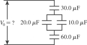
Free
(Short Answer)
4.8/5 (38)
Correct Answer:Verified
(a) 1.50 V (b) 13.5 μJ
Three resistors with resistances of 2.0 Ω, 6.0 Ω, and 12 Ω are connected across an ideal dc voltage source V as shown in the figure. If the total current through the circuit is I = 2.0 A, what is the applied voltage V? 
Free
(Multiple Choice)
4.9/5 (28)
Correct Answer:Verified
D
A combination of a 2.0-Ω resistor in series with 4.0-Ω resistor is connected in parallel with a 3.0-Ω resistor. What is the equivalent resistance of this system?
(Multiple Choice)
4.8/5 (43)
A 5.0-μF and a 12.0-μF capacitor are connected in series, and the series arrangement is connected in parallel to a capacitor. How much capacitance would a single capacitor need to replace this combination of three capacitors?
(Multiple Choice)
4.8/5 (41)
A charged capacitor is connected in series with a resistor and an open switch. At time t = 0 s, the switch is closed. Which of the graphs below best describes the current I through the resistor as a function of time t?
(Multiple Choice)
4.8/5 (33)
In the circuit shown in the figure, R1 = R2 = 90.0 Ω, R3 = R4 = 20.0 Ω, V1 = 7.0 V, V2 = 8.0 V, and the batteries are both ideal. What current does the ammeter read? 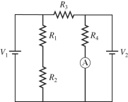
(Multiple Choice)
4.9/5 (35)
What is the magnitude of the potential difference between points A and C for the circuit shown in the figure? The battery is ideal, and all the numbers are accurate to two significant figures. 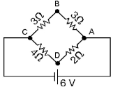
(Multiple Choice)
4.8/5 (30)
Two resistors in series are equivalent to 9.0 Ω, and in parallel they are equivalent to 2.0 Ω. What are the resistances of these two resistors?
(Short Answer)
4.8/5 (31)
For the circuit shown in the figure, C = 12 µF and R = 8.5 MΩ. Initially the switch S is open with the capacitor charged to a voltage of 80 V. The switch is then closed at time t = 0.00 s. What is the charge on the capacitor, when the current in the circuit is 3.3 µA? 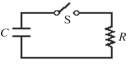
(Multiple Choice)
4.8/5 (33)
For the circuit shown in the figure, R1 = 18 Ω, R2 = 44 Ω, R3 = 33 Ω, R4 = 14 Ω, R5 = 12 Ω, V1 = 18 V, V2 = 12 V, and the batteries are ideal. Determine I1 and I2. 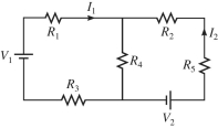
(Short Answer)
4.8/5 (35)
A fully charged 37-µF capacitor is discharged through a 1.0-kΩ resistor. If the voltage across the capacitor is reduced to 7.6 volts after just 20 ms, what was the original potential across the capacitor?
(Multiple Choice)
4.8/5 (34)
Three resistors with resistances of 2.0 Ω, 6.0 Ω, and 12 Ω are connected across an ideal dc voltage source V, as shown in the figure. If the total current in the circuit is I = 5.0 A, what is the current through the 12-Ω resistor? 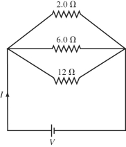
(Multiple Choice)
4.8/5 (33)
For the circuit shown in the figure, R1 = 5.6 Ω, R2 = 5.6 Ω, R3 = 14 Ω, and ε = 6.0 V, and the battery is ideal.
(a) What is the equivalent resistance across the battery?
(b) Find the current through each resistor. 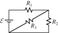
(Short Answer)
4.9/5 (29)
An ideal 100-V dc battery is applied across a series combination of four resistors having resistances of 20 Ω, 40 Ω, 60 Ω, and 80 Ω. What is the potential difference across the 40-Ω resistor?
(Multiple Choice)
4.8/5 (40)
A number of resistors are connected across points A and B as shown in the figure. What is the equivalent resistance between points A and B? 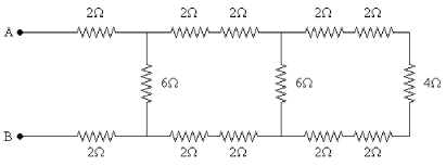
(Multiple Choice)
4.9/5 (38)
If emf of the ideal battery is V = 100 V, what is the potential difference across R5 for the circuit shown in the figure? 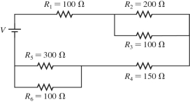
(Multiple Choice)
4.8/5 (41)
What is the equivalent resistance between points A and B of the network shown in the figure? 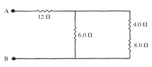
(Short Answer)
5.0/5 (33)
Three capacitors of equal capacitance are arranged as shown in the figure, with a voltage source across the combination. If the voltage drop across C1 is what is the voltage drop across 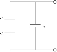
(Multiple Choice)
4.8/5 (44)
A portion of a circuit is shown in the figure, and the batteries are ideal. What is the potential difference VA - VB if I = 5.0 A? 
(Multiple Choice)
4.9/5 (27)
Filters
- Essay(0)
- Multiple Choice(0)
- Short Answer(0)
- True False(0)
- Matching(0)