Deck 10: Rccircuits
Full screen (f)
Question
Question
Question
Question
Question
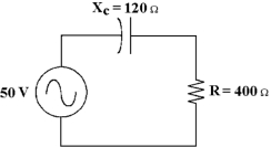
If the operating frequency increases in Figure 10 -1, how does the resistor value change?
A)It remains the same.
B)It opens.
C)It decreases.
D)It increases.
Question
Question
What is the circuit's impedance in Figure 10 -1?
A)520 Ω
B)418 Ω
C)280 Ω
D)120 Ω
Question
What is the true power in Figure 10 -1?
A)5.73 W
B)916 mW
C)275 mW
D)5.73 mW
Question
Question
Question
Question
Question
Question
Question
If the operating frequency increases in Figure 10 -1, how does the phase angle change?
A)It changes to another quadrant.
B)It increases.
C)It remains the name.
D)It decreases.
Question
If the operating frequency increases in Figure 10 -1, how does the current change?
A)It remains the same.
B)It increases.
C)It decreases.
D)It decreases to zero.
Question
Question
If the frequency equals 60 Hz in Figure 10 -1, what is the value of capacitance?
A)88 µF
B)66 µF
C)22 µF
D)44 µF
Question
Question
Question
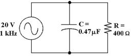
Which statement describes the relationship of IC and IR in Figure 10 -2?
A)They are in phase.
B)IC leads IR.
C)They are 180° out of phase.
D)IC lags IR.
Question
If the frequency decreases in Figure 10 -1, the phase angle and the impedance _.
A)decreases, decreases
B)increases, increases
C)increases, decreases
D)decreases, increases
Question
If the operating frequency decreases in Figure 10 -1, how does the resistance value change?
A)It decreases.
B)It increases.
C)It opens.
D)It remains the same.
Question
If the operating frequency decreases in Figure 10 -1, how does the current change?
A)It decreases.
B)It increases.
C)It remains the same.
D)It decreases to zero.
Question
How much voltage does the resistor drop in Figure 10 -2?
A)59 mV
B)19.94 V
C)20 V
D)10 V
Question
If the frequency is 400 Hz in Figure 10 -1, what is the value of capacitance?
A)10 µF
B)6.6 µF
C)8.8 µF
D)3.3 µF
Question
If the operating frequency decreases in Figure 10 -1, how does the capacitance value change?
A)It remains the same.
B)It decreases.
C)It increases.
D)It decreases to zero.
Question
If the source voltage is changed to 100 V in Figure 10 -1, find the true power.
A)3.66 W
B)22.9 W
C)11 W
D)22.9 mW
Question
What change would decrease the power factor in Figure 10 -2?
A)increasing the value of the resistor
B)increasing the value of Vs
C)decreasing the value of the capacitor
D)increasing the value of the capacitor
Question
If the resistor changes to 2.2 kΩ in Figure 10 -1, how does the total current change?
A)It decreases.
B)It decreases to zero.
C)It increases.
D)It remains the same.
Question
If the operating frequency decreases in Figure 10 -1, how does the phase angle change?
A)It decreases.
B)It increases.
C)It changes to another quadrant.
D)It remains the same.
Question
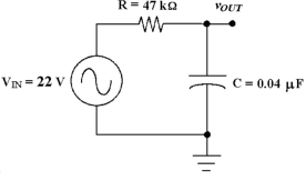
The circuit in Figure 10 -3 is known as a _ .
A)band -pass filter
B)high -pass filter
C)parallel RC circuit
D)low -pass filter
Question
Calculate the voltage drop across the capacitor in Figure 10 -1.
A)3.69 V
B)4.82 V
C)11.5 V
D)14.4 V
Question
If the resistor value increases in Figure 10 -2, then how does the total current change?
A)It decreases to zero.
B)It increases.
C)It decreases.
D)It remains the same.
Question
What change would increase the power factor in Figure 10 -2?
A)Increasing the value of the source voltage
B)Increasing the value of the capacitor
C)Decreasing the value of the capacitor
D)Increasing the value of the resistor
Question
Calculate the total impedance in Figure 10 -2.
A)880 Ω
B)1000 Ω
C)258 Ω
D)62 Ω
Question
How much voltage does the capacitor drop in Figure 10 -2?
A)59 mV
B)10 V
C)20 V
D)19.94 V
Question
Calculate the apparent power in Figure 10 -1.
A)5.66 VA
B)5.99 VA
C)14.37 VA
D)1.70 VA
Question
What is the cutoff frequency in Figure 10 -3?
A)1012 Hz
B)85 Hz
C)118 Hz
D)995 Hz
Question
If the frequency increases in Figure 10 -1, the phase angle and the impedance _.
A)decreases, increases
B)increases, increases
C)decreases, decreases
D)increases, decreases
Question
Question
Question
Question
If the input voltage increases to 50 V in Figure 10 -3, what is the output voltage at the cutoff frequency?
A)35.4 V
B)17.7 V
C)70.7 V
D)8.84 V
Question
Question
What is the circuit fault in Figure 10 -3 if the output voltage equals 0 V at the cutoff frequency?
A)The capacitor has opened.
B)The capacitor has become leaky.
C)The capacitor has shorted.
D)The resistor has shorted.
Question
If the circuit in Figure 10 -3 has an output voltage that's too high at the cutoff frequency, .
A)the resistor has opened
B)the capacitor has become leaky
C)the capacitor has shorted
D)the resistor has shorted
Question
Question
Question
Question
Question
If the resistor changes to 2.2 kΩ in Figure 10 -3, the new cutoff frequency equals .
A)1.18 kHz
B)995 Hz
C)1.81 kHz
D)1.01 kHz
Question
Question
What is the output voltage at the cutoff frequency in Figure 10 -3?
A)31.1 V
B)6.45 V
C)15.6 V
D)22 V
Question
Question
If the resistance is reduced to 4 kΩ in Figure 10 -3, the cutoff frequency equals .
A)480 Hz
B)6250 Hz
C)995 Hz
D)99 Hz
Question
If the resistor is changed to 100 kΩ in Figure 10 -3, what is the new cutoff frequency?
A)79.6 Hz
B)318 Hz
C)159 Hz
D)39.8 Hz
Question
Question
Question
If the output were taken across the resistor in Figure 10 -3, the circuit would be known as a .
A)low -pass filter
B)band -notch filter
C)band -pass filter
D)high -pass filter
Question
Question
Question
Question
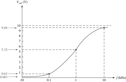
This frequency response curve in Figure 10 -4 represents what type of filter?
A)band pass
B)low pass
C)high pass
D)band stop
Question
Question

Unlock Deck
Sign up to unlock the cards in this deck!
Unlock Deck
Unlock Deck
1/66
Play
Full screen (f)
Deck 10: Rccircuits
1
As the frequency applied to an RC circuit varies, both XC and resistance vary.
False
2
A leaky capacitor can be equated as a capacitor with a resistor being placed in series with it.
False
3
When the frequency applied to an RC circuit varies, the value of XC varies.
True
4
As the frequency applied to an RC circuit is decreased, the phase angle decreases.
Unlock Deck
Unlock for access to all 66 flashcards in this deck.
Unlock Deck
k this deck
5
If the operating frequency increases in Figure 10 -1, how does the resistor value change?
A)It remains the same.
B)It opens.
C)It decreases.
D)It increases.
Unlock Deck
Unlock for access to all 66 flashcards in this deck.
Unlock Deck
k this deck
6
Power factor values close to 0 denotes an RC circuit with mostly true power.
Unlock Deck
Unlock for access to all 66 flashcards in this deck.
Unlock Deck
k this deck
7
What is the circuit's impedance in Figure 10 -1?
A)520 Ω
B)418 Ω
C)280 Ω
D)120 Ω
Unlock Deck
Unlock for access to all 66 flashcards in this deck.
Unlock Deck
k this deck
8
What is the true power in Figure 10 -1?
A)5.73 W
B)916 mW
C)275 mW
D)5.73 mW
Unlock Deck
Unlock for access to all 66 flashcards in this deck.
Unlock Deck
k this deck
9
The total current in an RC circuit always lags the source voltage.
Unlock Deck
Unlock for access to all 66 flashcards in this deck.
Unlock Deck
k this deck
10
As the frequency applied to an RC circuit increases, the impedance decreases.
Unlock Deck
Unlock for access to all 66 flashcards in this deck.
Unlock Deck
k this deck
11
The phasor combination of XC and R is called Z.
Unlock Deck
Unlock for access to all 66 flashcards in this deck.
Unlock Deck
k this deck
12
The phase angle of an RC circuit varies inversely with frequency.
Unlock Deck
Unlock for access to all 66 flashcards in this deck.
Unlock Deck
k this deck
13
A high pass filter will cause some phase shifting of the signal.
Unlock Deck
Unlock for access to all 66 flashcards in this deck.
Unlock Deck
k this deck
14
The phasor combination of VR and VC in an RC series circuit equals the source voltage.
Unlock Deck
Unlock for access to all 66 flashcards in this deck.
Unlock Deck
k this deck
15
If the operating frequency increases in Figure 10 -1, how does the phase angle change?
A)It changes to another quadrant.
B)It increases.
C)It remains the name.
D)It decreases.
Unlock Deck
Unlock for access to all 66 flashcards in this deck.
Unlock Deck
k this deck
16
If the operating frequency increases in Figure 10 -1, how does the current change?
A)It remains the same.
B)It increases.
C)It decreases.
D)It decreases to zero.
Unlock Deck
Unlock for access to all 66 flashcards in this deck.
Unlock Deck
k this deck
17
A VA rating is more relevant when judging the current delivery capacity for a given signal source.
Unlock Deck
Unlock for access to all 66 flashcards in this deck.
Unlock Deck
k this deck
18
If the frequency equals 60 Hz in Figure 10 -1, what is the value of capacitance?
A)88 µF
B)66 µF
C)22 µF
D)44 µF
Unlock Deck
Unlock for access to all 66 flashcards in this deck.
Unlock Deck
k this deck
19
The total current in an RC circuit always leads the source voltage.
Unlock Deck
Unlock for access to all 66 flashcards in this deck.
Unlock Deck
k this deck
20
An RC circuit can be used as a filter to eliminate selected frequencies.
Unlock Deck
Unlock for access to all 66 flashcards in this deck.
Unlock Deck
k this deck
21
Which statement describes the relationship of IC and IR in Figure 10 -2?
A)They are in phase.
B)IC leads IR.
C)They are 180° out of phase.
D)IC lags IR.
Unlock Deck
Unlock for access to all 66 flashcards in this deck.
Unlock Deck
k this deck
22
If the frequency decreases in Figure 10 -1, the phase angle and the impedance _.
A)decreases, decreases
B)increases, increases
C)increases, decreases
D)decreases, increases
Unlock Deck
Unlock for access to all 66 flashcards in this deck.
Unlock Deck
k this deck
23
If the operating frequency decreases in Figure 10 -1, how does the resistance value change?
A)It decreases.
B)It increases.
C)It opens.
D)It remains the same.
Unlock Deck
Unlock for access to all 66 flashcards in this deck.
Unlock Deck
k this deck
24
If the operating frequency decreases in Figure 10 -1, how does the current change?
A)It decreases.
B)It increases.
C)It remains the same.
D)It decreases to zero.
Unlock Deck
Unlock for access to all 66 flashcards in this deck.
Unlock Deck
k this deck
25
How much voltage does the resistor drop in Figure 10 -2?
A)59 mV
B)19.94 V
C)20 V
D)10 V
Unlock Deck
Unlock for access to all 66 flashcards in this deck.
Unlock Deck
k this deck
26
If the frequency is 400 Hz in Figure 10 -1, what is the value of capacitance?
A)10 µF
B)6.6 µF
C)8.8 µF
D)3.3 µF
Unlock Deck
Unlock for access to all 66 flashcards in this deck.
Unlock Deck
k this deck
27
If the operating frequency decreases in Figure 10 -1, how does the capacitance value change?
A)It remains the same.
B)It decreases.
C)It increases.
D)It decreases to zero.
Unlock Deck
Unlock for access to all 66 flashcards in this deck.
Unlock Deck
k this deck
28
If the source voltage is changed to 100 V in Figure 10 -1, find the true power.
A)3.66 W
B)22.9 W
C)11 W
D)22.9 mW
Unlock Deck
Unlock for access to all 66 flashcards in this deck.
Unlock Deck
k this deck
29
What change would decrease the power factor in Figure 10 -2?
A)increasing the value of the resistor
B)increasing the value of Vs
C)decreasing the value of the capacitor
D)increasing the value of the capacitor
Unlock Deck
Unlock for access to all 66 flashcards in this deck.
Unlock Deck
k this deck
30
If the resistor changes to 2.2 kΩ in Figure 10 -1, how does the total current change?
A)It decreases.
B)It decreases to zero.
C)It increases.
D)It remains the same.
Unlock Deck
Unlock for access to all 66 flashcards in this deck.
Unlock Deck
k this deck
31
If the operating frequency decreases in Figure 10 -1, how does the phase angle change?
A)It decreases.
B)It increases.
C)It changes to another quadrant.
D)It remains the same.
Unlock Deck
Unlock for access to all 66 flashcards in this deck.
Unlock Deck
k this deck
32
The circuit in Figure 10 -3 is known as a _ .
A)band -pass filter
B)high -pass filter
C)parallel RC circuit
D)low -pass filter
Unlock Deck
Unlock for access to all 66 flashcards in this deck.
Unlock Deck
k this deck
33
Calculate the voltage drop across the capacitor in Figure 10 -1.
A)3.69 V
B)4.82 V
C)11.5 V
D)14.4 V
Unlock Deck
Unlock for access to all 66 flashcards in this deck.
Unlock Deck
k this deck
34
If the resistor value increases in Figure 10 -2, then how does the total current change?
A)It decreases to zero.
B)It increases.
C)It decreases.
D)It remains the same.
Unlock Deck
Unlock for access to all 66 flashcards in this deck.
Unlock Deck
k this deck
35
What change would increase the power factor in Figure 10 -2?
A)Increasing the value of the source voltage
B)Increasing the value of the capacitor
C)Decreasing the value of the capacitor
D)Increasing the value of the resistor
Unlock Deck
Unlock for access to all 66 flashcards in this deck.
Unlock Deck
k this deck
36
Calculate the total impedance in Figure 10 -2.
A)880 Ω
B)1000 Ω
C)258 Ω
D)62 Ω
Unlock Deck
Unlock for access to all 66 flashcards in this deck.
Unlock Deck
k this deck
37
How much voltage does the capacitor drop in Figure 10 -2?
A)59 mV
B)10 V
C)20 V
D)19.94 V
Unlock Deck
Unlock for access to all 66 flashcards in this deck.
Unlock Deck
k this deck
38
Calculate the apparent power in Figure 10 -1.
A)5.66 VA
B)5.99 VA
C)14.37 VA
D)1.70 VA
Unlock Deck
Unlock for access to all 66 flashcards in this deck.
Unlock Deck
k this deck
39
What is the cutoff frequency in Figure 10 -3?
A)1012 Hz
B)85 Hz
C)118 Hz
D)995 Hz
Unlock Deck
Unlock for access to all 66 flashcards in this deck.
Unlock Deck
k this deck
40
If the frequency increases in Figure 10 -1, the phase angle and the impedance _.
A)decreases, increases
B)increases, increases
C)decreases, decreases
D)increases, decreases
Unlock Deck
Unlock for access to all 66 flashcards in this deck.
Unlock Deck
k this deck
41
A power factor of 1 indicates that the circuit phase angle is .
A)90°
B)0°
C)180°
D)45°
A)90°
B)0°
C)180°
D)45°
Unlock Deck
Unlock for access to all 66 flashcards in this deck.
Unlock Deck
k this deck
42
In a series RC circuit, as the phase angle between the applied voltage and the total current increases, this is the same as:
A)power factor increasing.
B)apparent power decreasing.
C)true power decreasing.
D)power factor decreasing.
A)power factor increasing.
B)apparent power decreasing.
C)true power decreasing.
D)power factor decreasing.
Unlock Deck
Unlock for access to all 66 flashcards in this deck.
Unlock Deck
k this deck
43
In an RC circuit, the capacitive reactance is:
A)decreases as the frequency increases.
B)inversely proportional to the capacitance.
C)inversely proportional to the frequency.
D)all of these.
A)decreases as the frequency increases.
B)inversely proportional to the capacitance.
C)inversely proportional to the frequency.
D)all of these.
Unlock Deck
Unlock for access to all 66 flashcards in this deck.
Unlock Deck
k this deck
44
If the input voltage increases to 50 V in Figure 10 -3, what is the output voltage at the cutoff frequency?
A)35.4 V
B)17.7 V
C)70.7 V
D)8.84 V
Unlock Deck
Unlock for access to all 66 flashcards in this deck.
Unlock Deck
k this deck
45
An RC lag network is similar to a:
A)high pass filter.
B)low pass filter.
C)stop pass filter.
D)band pass filter.
A)high pass filter.
B)low pass filter.
C)stop pass filter.
D)band pass filter.
Unlock Deck
Unlock for access to all 66 flashcards in this deck.
Unlock Deck
k this deck
46
What is the circuit fault in Figure 10 -3 if the output voltage equals 0 V at the cutoff frequency?
A)The capacitor has opened.
B)The capacitor has become leaky.
C)The capacitor has shorted.
D)The resistor has shorted.
Unlock Deck
Unlock for access to all 66 flashcards in this deck.
Unlock Deck
k this deck
47
If the circuit in Figure 10 -3 has an output voltage that's too high at the cutoff frequency, .
A)the resistor has opened
B)the capacitor has become leaky
C)the capacitor has shorted
D)the resistor has shorted
Unlock Deck
Unlock for access to all 66 flashcards in this deck.
Unlock Deck
k this deck
48
In a X10 oscilloscope probe input resistance is factor of 10. _ and input capacitance is
_ by a
A)increased, decreased
B)decreased, increased
C)decreased, decreased
D)increased, increased
_ by a
A)increased, decreased
B)decreased, increased
C)decreased, decreased
D)increased, increased
Unlock Deck
Unlock for access to all 66 flashcards in this deck.
Unlock Deck
k this deck
49
Power in an RC circuit can be measured as:
A)apparent power (Pa).
B)reactive power (Pr).
C)true power (Ptrue).
D)all of these.
A)apparent power (Pa).
B)reactive power (Pr).
C)true power (Ptrue).
D)all of these.
Unlock Deck
Unlock for access to all 66 flashcards in this deck.
Unlock Deck
k this deck
50
When an AC voltage is supplied to an RC circuit, the AC's current and amplitude will be:
A)leading the voltage.
B)varying in the same manner.
C)similar in waveform.
D)all of these.
A)leading the voltage.
B)varying in the same manner.
C)similar in waveform.
D)all of these.
Unlock Deck
Unlock for access to all 66 flashcards in this deck.
Unlock Deck
k this deck
51
If the bandwidth of a low -pass filter is 0 to 1 kHz, the cutoff frequency is .
A)2 kHz
B)0 Hz
C)1 kHz
D)500 Hz
A)2 kHz
B)0 Hz
C)1 kHz
D)500 Hz
Unlock Deck
Unlock for access to all 66 flashcards in this deck.
Unlock Deck
k this deck
52
If the resistor changes to 2.2 kΩ in Figure 10 -3, the new cutoff frequency equals .
A)1.18 kHz
B)995 Hz
C)1.81 kHz
D)1.01 kHz
Unlock Deck
Unlock for access to all 66 flashcards in this deck.
Unlock Deck
k this deck
53
If there is 10 VRMS across the resistor and 10 VRMS across the capacitor in a series RC circuit, then the source voltage equals _.
A)20 VRMS
B)28.3 VRMS
C)10 VRMS
D)14.1 VRMS
A)20 VRMS
B)28.3 VRMS
C)10 VRMS
D)14.1 VRMS
Unlock Deck
Unlock for access to all 66 flashcards in this deck.
Unlock Deck
k this deck
54
What is the output voltage at the cutoff frequency in Figure 10 -3?
A)31.1 V
B)6.45 V
C)15.6 V
D)22 V
Unlock Deck
Unlock for access to all 66 flashcards in this deck.
Unlock Deck
k this deck
55
An RC high pass filter takes its output across:
A)the series resistor.
B)the parallel capacitor.
C)the series capacitor.
D)the parallel resistor.
A)the series resistor.
B)the parallel capacitor.
C)the series capacitor.
D)the parallel resistor.
Unlock Deck
Unlock for access to all 66 flashcards in this deck.
Unlock Deck
k this deck
56
If the resistance is reduced to 4 kΩ in Figure 10 -3, the cutoff frequency equals .
A)480 Hz
B)6250 Hz
C)995 Hz
D)99 Hz
Unlock Deck
Unlock for access to all 66 flashcards in this deck.
Unlock Deck
k this deck
57
If the resistor is changed to 100 kΩ in Figure 10 -3, what is the new cutoff frequency?
A)79.6 Hz
B)318 Hz
C)159 Hz
D)39.8 Hz
Unlock Deck
Unlock for access to all 66 flashcards in this deck.
Unlock Deck
k this deck
58
If there is 1 ARMS through the resistor and 1 ARMS through the capacitor in a parallel RC circuit, then the total current equals .
A)2 ARMS
B)2.28 ARMS
C)1.41 ARMS
D)1 ARMS
A)2 ARMS
B)2.28 ARMS
C)1.41 ARMS
D)1 ARMS
Unlock Deck
Unlock for access to all 66 flashcards in this deck.
Unlock Deck
k this deck
59
If the true power is 100 W and the reactive power is 100 VAR, the apparent power is .
A)141 VA
B)200 VA
C)141 W
D)100 VA
A)141 VA
B)200 VA
C)141 W
D)100 VA
Unlock Deck
Unlock for access to all 66 flashcards in this deck.
Unlock Deck
k this deck
60
If the output were taken across the resistor in Figure 10 -3, the circuit would be known as a .
A)low -pass filter
B)band -notch filter
C)band -pass filter
D)high -pass filter
Unlock Deck
Unlock for access to all 66 flashcards in this deck.
Unlock Deck
k this deck
61
In an RC filter circuit, the cutoff frequency is defined as the frequency at which:
A)the output voltage drops to 33% of maximum.
B)the output voltage is cutoff, with minimum or zero output.
C)the output voltage drops to 66% of maximum.
D)the output voltage drops to 70% of maximum.
A)the output voltage drops to 33% of maximum.
B)the output voltage is cutoff, with minimum or zero output.
C)the output voltage drops to 66% of maximum.
D)the output voltage drops to 70% of maximum.
Unlock Deck
Unlock for access to all 66 flashcards in this deck.
Unlock Deck
k this deck
62
Which of these troubleshooting procedures should be performed first?
A)Slap the device firmly to dislodge foreign objects.
B)Check test equipment connections.
C)Take random measurements around point of failure.
D)Analyze the problem and decide where best to start.
A)Slap the device firmly to dislodge foreign objects.
B)Check test equipment connections.
C)Take random measurements around point of failure.
D)Analyze the problem and decide where best to start.
Unlock Deck
Unlock for access to all 66 flashcards in this deck.
Unlock Deck
k this deck
63
It has been determined that the phase shift of a given parallel RC circuit is lower than predicted. Which of the following most likely has caused this?
A)Resistance has decreased.
B)The function generator frequency control has been accidentally moved to a lower frequency.
C)The capacitance has decreased.
D)could be A or C
A)Resistance has decreased.
B)The function generator frequency control has been accidentally moved to a lower frequency.
C)The capacitance has decreased.
D)could be A or C
Unlock Deck
Unlock for access to all 66 flashcards in this deck.
Unlock Deck
k this deck
64
This frequency response curve in Figure 10 -4 represents what type of filter?
A)band pass
B)low pass
C)high pass
D)band stop
Unlock Deck
Unlock for access to all 66 flashcards in this deck.
Unlock Deck
k this deck
65
Simple RC circuits can be viewed as what type of filter?
A)passive
B)low pass
C)active
D)high pass
A)passive
B)low pass
C)active
D)high pass
Unlock Deck
Unlock for access to all 66 flashcards in this deck.
Unlock Deck
k this deck
66
The output voltage of an RC high pass filter at a designated frequency is low. What is a possible problem?
A)shorted capacitor
B)open resistor
C)not enough information
D)function generator misadjusted
A)shorted capacitor
B)open resistor
C)not enough information
D)function generator misadjusted
Unlock Deck
Unlock for access to all 66 flashcards in this deck.
Unlock Deck
k this deck
Unlock Deck
Unlock for access to all 66 flashcards in this deck.


