Exam 10: Rccircuits
Exam 1: Systems, Quantities, and Units41 Questions
Exam 2: Voltage, Current, and Resistance71 Questions
Exam 3: Ohms Law, Energy, and Power69 Questions
Exam 4: Series Circuits67 Questions
Exam 5: Parallel Circuits66 Questions
Exam 6: Series-Parallel Circuits73 Questions
Exam 7: Magnetism and Electromagnetism69 Questions
Exam 8: Introduction to Alternating Current and Voltage74 Questions
Exam 9: Capacitors69 Questions
Exam 10: Rccircuits66 Questions
Exam 11: Inductors66 Questions
Exam 12: Rlcircuits67 Questions
Exam 13: Rlccircuits and Resonance70 Questions
Exam 14: Transformers69 Questions
Exam 15: Time Response of Reactive Circuits68 Questions
Select questions type
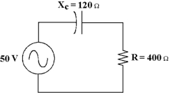
 -How much voltage does the resistor drop in Figure 10 -2?
Free
(Multiple Choice)
4.9/5  (34)
(34)
Correct Answer: Verified
C
An RC circuit can be used as a filter to eliminate selected frequencies.
Free
(True/False)
4.9/5 (31)
Correct Answer:Verified
True
-How much voltage does the capacitor drop in Figure 10 -2?
Free
(Multiple Choice)
4.8/5 (30)
Correct Answer:Verified
C
As the frequency applied to an RC circuit varies, both XC and resistance vary.
(True/False)
4.9/5 (39)
If there is 1 ARMS through the resistor and 1 ARMS through the capacitor in a parallel RC circuit, then the total current equals .
(Multiple Choice)
4.7/5 (34)
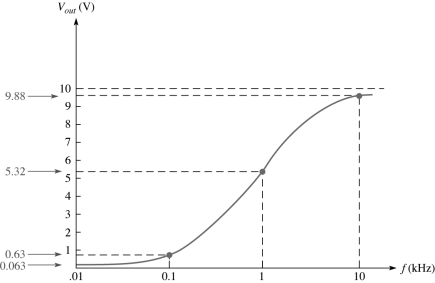 -This frequency response curve in Figure 10 -4 represents what type of filter?
(Multiple Choice)
4.7/5 (32)
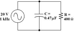
 -If the frequency equals 60 Hz in Figure 10 -1, what is the value of capacitance?
(Multiple Choice)
4.9/5 (35)
A VA rating is more relevant when judging the current delivery capacity for a given signal source.
(True/False)
4.7/5 (28)
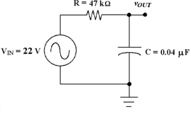 -What is the circuit fault in Figure 10 -3 if the output voltage equals 0 V at the cutoff frequency?
(Multiple Choice)
4.9/5 (36)
If the true power is 100 W and the reactive power is 100 VAR, the apparent power is .
(Multiple Choice)
4.8/5 (36)
If the bandwidth of a low -pass filter is 0 to 1 kHz, the cutoff frequency is .
(Multiple Choice)
4.9/5 (41)
-If the resistor value increases in Figure 10 -2, then how does the total current change?
(Multiple Choice)
4.7/5 (34)
-Calculate the voltage drop across the capacitor in Figure 10 -1.
(Multiple Choice)
4.9/5 (33)
-If the operating frequency decreases in Figure 10 -1, how does the phase angle change?
(Multiple Choice)
4.8/5 (23)
A power factor of 1 indicates that the circuit phase angle is .
(Multiple Choice)
4.8/5 (35)
The total current in an RC circuit always lags the source voltage.
(True/False)
5.0/5 (22)
Filters
- Essay(0)
- Multiple Choice(0)
- Short Answer(0)
- True False(0)
- Matching(0)