Deck 31: Fundamentals of Circuits
Full screen (f)
Question
Question
Question
Question
In the circuit shown in the figure, an ideal ohmmeter is connected across ab with the switch S open. All the connecting leads have negligible resistance. The reading of the ohmmeter will be closest to 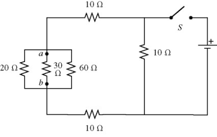
A) 7.5 Ω.
B) 10 Ω.
C) 30 Ω.
D) 40 Ω.
E) 60 Ω.
A) 7.5 Ω.
B) 10 Ω.
C) 30 Ω.
D) 40 Ω.
E) 60 Ω.
Question
Four resistors are connected across an 8-V DC battery as shown in the figure. The current through the 9-Ω resistor is closest to 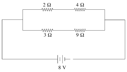
A) 1 A.
B) 0.7 A.
C) 0.5 A.
D) 0.9 A.
E) 2 A.
A) 1 A.
B) 0.7 A.
C) 0.5 A.
D) 0.9 A.
E) 2 A.
Question
Two light bulbs, B1 and B2, are connected to a battery having appreciable internal resistance as shown in the figure. What happens to the brightness of bulb B1 when we close the switch S? 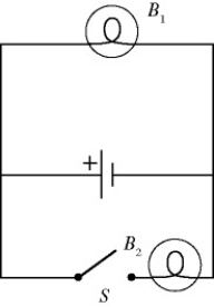
A) The brightness of B1 increases permanently.
B) The brightness of B1 decreases permanently.
C) The brightness of B1 does not change.
D) The brightness of B1 increases temporarily but gradually decreases back to its original brightness.
E) The brightness of B1 decreases temporarily but gradually increases back to its original brightness.
Question
Three resistors are connected across an ideal 2.0-V DC battery as shown in the figure.
(a) At what rate does the battery supply energy to the resistors?
(b) At what rate is heat produced in the 6.0-Ω resistor?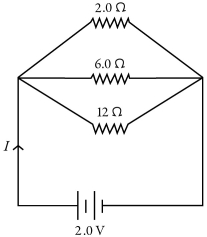
(a) At what rate does the battery supply energy to the resistors?
(b) At what rate is heat produced in the 6.0-Ω resistor?
Question
Thirteen resistors are connected across points A and B as shown in the figure. If all the resistors are accurate to 2 significant figures, what is the equivalent resistance between points A and B? 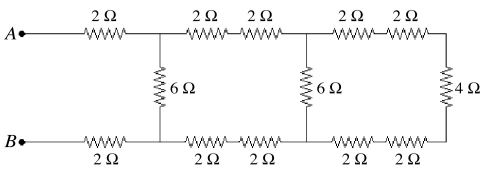
A) 4.0 Ω
B) 6.0 Ω
C) 8.0 Ω
D) 10 Ω
E) 12 Ω
A) 4.0 Ω
B) 6.0 Ω
C) 8.0 Ω
D) 10 Ω
E) 12 Ω
Question
In the circuit shown in the figure, all the lightbulbs are identical. Which of the following is the correct ranking of the brightness of the bulbs? 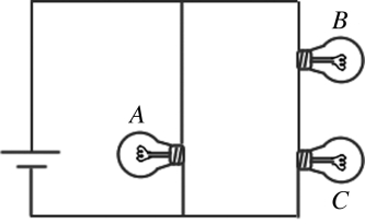
A) B and C have equal brightness, and A is the dimmest.
B) A and B have equal brightness, and C is the dimmest.
C) A is brightest, C is dimmest, and B is in between.
D) A is the brightest, and B and C have equal brightness but less than A.
E) All three bulbs have the same brightness.
A) B and C have equal brightness, and A is the dimmest.
B) A and B have equal brightness, and C is the dimmest.
C) A is brightest, C is dimmest, and B is in between.
D) A is the brightest, and B and C have equal brightness but less than A.
E) All three bulbs have the same brightness.
Question
Question
A galvanometer G has an internal resistance rg. A VOLTMETER is constructed by incorporating the galvanometer and an additional resistance Rs. Which one of the figures below is the most appropriate circuit diagram for the voltmeter? 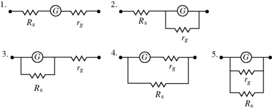
A) 1
B) 2
C) 3
D) 4
E) 5
A) 1
B) 2
C) 3
D) 4
E) 5
Question
A light bulb is connected in the circuit shown in the figure with the switch S open and the capacitor uncharged. The battery has no appreciable internal resistance. Which one of the following graphs best describes the brightness B of the bulb as a function of time t after closing the switch? 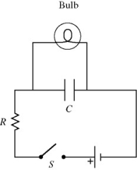
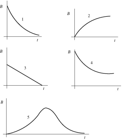
A) 1
B) 2
C) 3
D) 4
E) 5
A) 1
B) 2
C) 3
D) 4
E) 5
Question
A light bulb is connected in the circuit shown in the figure with the switch S open. All the connecting leads have no appreciable resistance and the battery has no internal resistance. When we close the switch, which statements below accurately describe the behavior of the circuit? (There may be more than one correct choice.) 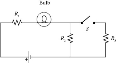
A) The brightness of the bulb will increase.
B) The brightness of the bulb will decrease.
C) The brightness of the bulb will not change.
D) The potential drop across R2 will decrease.
E) The potential drop across R2 will not change.
A) The brightness of the bulb will increase.
B) The brightness of the bulb will decrease.
C) The brightness of the bulb will not change.
D) The potential drop across R2 will decrease.
E) The potential drop across R2 will not change.
Question
The figure shows three identical lightbulbs connected to a battery having a constant voltage across its terminals. What happens to the brightness of lightbulb 1 when the switch S is closed? 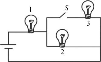
A) The brightness will increase momentarily then return to its previous level.
B) The brightness increases permanently.
C) The brightness will decrease momentarily then return to its previous level.
D) The brightness remains the same as before the switch is closed.
E) The brightness decreases permanently.
Question
For the circuit shown in the figure, determine the current in
(a) the 1.0-Ω resistor.
(b) the 3.0-Ω resistor.
(c) the 4.0-Ω resistor.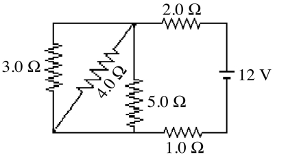
(a) the 1.0-Ω resistor.
(b) the 3.0-Ω resistor.
(c) the 4.0-Ω resistor.
Question
Question
A galvanometer G has an internal resistance rg. An AMMETER is constructed by incorporating the galvanometer and an additional resistance Rs. Which one of the figures below is the most appropriate circuit diagram for the ammeter? 
A) 1
B) 2
C) 3
D) 4
E) 5
A) 1
B) 2
C) 3
D) 4
E) 5
Question
Question
Question
In the circuit shown in the figure, four identical resistors labeled A to D are connected to a battery as shown. S1 and S2 are switches. Which of the following actions would result in the GREATEST amount of current through resistor A? 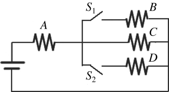
A) closing both switches
B) closing S1 only
C) closing S2 only
D) leaving both switches open as shown.
A) closing both switches
B) closing S1 only
C) closing S2 only
D) leaving both switches open as shown.
Question
For the circuit shown in the figure, what current does the ideal ammeter read? 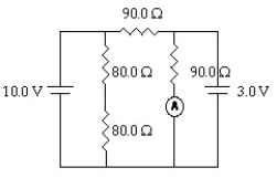
A) 0.033 A
B) 0.078 A
C) 0.23 A
D) 0.12 A
A) 0.033 A
B) 0.078 A
C) 0.23 A
D) 0.12 A
Question
Question
For the circuit shown in the figure, all quantities are accurate to 2 significant figures. What is the value of the current I1? 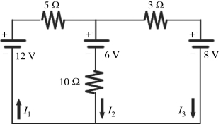
A) 0.32 A
B) 0.11 A
C) 0.29 A
D) 0.61 A
E) 0.89 A
A) 0.32 A
B) 0.11 A
C) 0.29 A
D) 0.61 A
E) 0.89 A
Question
When four identical resistors are connected to an ideal battery of voltage V = 10 V as shown in the figure, the current I is equal to 0.20 A. What is the value of the resistance R of the resistors? 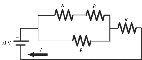
A) 20 Ω
B) 40 Ω
C) 30 Ω
D) 50 Ω
E) 10 Ω
A) 20 Ω
B) 40 Ω
C) 30 Ω
D) 50 Ω
E) 10 Ω
Question
For the circuit shown in the figure, the current in the 8-Ω resistor is 0.50 A, and all quantities are accurate to 2 significant figures. What is the current in the 2-Ω resistor? 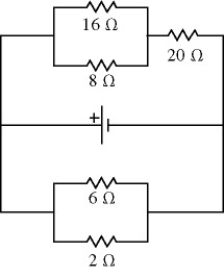
A) 2.25 A
B) 0.75 A
C) 4.5 A
D) 9.5 A
E) 6.4 A
A) 2.25 A
B) 0.75 A
C) 4.5 A
D) 9.5 A
E) 6.4 A
Question
Question
Consider the circuit shown in the figure. Note that two currents are shown. Calculate the emfs ε1 and ε3. 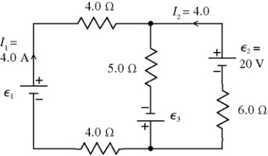
Question
A multiloop circuit is shown in the figure. Some circuit quantities are not labeled. It is not necessary to solve the entire circuit. The current I2 is closest to 
A) +0.1 A.
B) +0.3 A.
C) +0.5 A.
D) -0.1 A.
E) -0.3 A.
A) +0.1 A.
B) +0.3 A.
C) +0.5 A.
D) -0.1 A.
E) -0.3 A.
Question
A multiloop circuit is shown in the figure. Some circuit quantities are not labeled. It is not necessary to solve the entire circuit. The current I1 is closest to 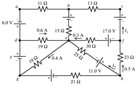
A) zero.
B) +0.2 A.
C) +0.4 A.
D) -0.2 A.
E) -0.4 A.
A) zero.
B) +0.2 A.
C) +0.4 A.
D) -0.2 A.
E) -0.4 A.
Question
A multiloop circuit is shown in the figure. Some circuit quantities are not labeled. It is not necessary to solve the entire circuit. The emf ε is closest to 
A) +3 V.
B) +19 V.
C) -3 V.
D) -10 V.
E) -1 V.
A) +3 V.
B) +19 V.
C) -3 V.
D) -10 V.
E) -1 V.
Question
Question
For the circuit shown in the figure, what is the current through resistor R3? 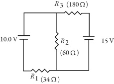
A) 0.043 A
B) 1.5 A
C) 0.028 A
D) 0.086 A
A) 0.043 A
B) 1.5 A
C) 0.028 A
D) 0.086 A
Question
Two identical resistors of resistance R = 24 Ω and a variable resistor Rx are connected to an ideal battery of voltage V as shown in the figure. What should be the value of the variable resistance Rx to make the voltage across the two parallel resistors equal to  .
. 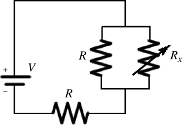
A) 4.0 Ω
B) 24 Ω
C) 8.0 Ω
D) 16 Ω
E) 40 Ω
. A) 4.0 Ω
B) 24 Ω
C) 8.0 Ω
D) 16 Ω
E) 40 Ω
Question
For the circuit shown in the figure, what is the current through resistor R1? 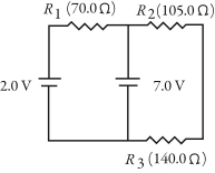
A) 0.071 A
B) 0.13 A
C) 0.029 A
D) 0.016 A
A) 0.071 A
B) 0.13 A
C) 0.029 A
D) 0.016 A
Question
A multiloop circuit is shown in the figure. It is not necessary to solve the entire circuit. The current I2 is closest to 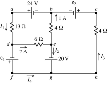
A) -6 A.
B) 6 A.
C) 8 A.
D) -8 A.
E) zero.
A) -6 A.
B) 6 A.
C) 8 A.
D) -8 A.
E) zero.
Question
Question
For the circuit shown in the figure, determine the current in
(a) the 7.0-Ω resistor.
(b) the 8.0-Ω resistor.
(c) the 4.0-Ω resistor.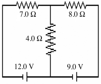
(a) the 7.0-Ω resistor.
(b) the 8.0-Ω resistor.
(c) the 4.0-Ω resistor.
Question
A multiloop circuit is shown in the figure. It is not necessary to solve the entire circuit. Compared to the polarity shown in the figure, the emf ε1 is closest to 
A) -5 V.
B) 5 V.
C) 45 V.
D) 51 V.
E) -51 V.
A) -5 V.
B) 5 V.
C) 45 V.
D) 51 V.
E) -51 V.
Question
For the circuit shown in the figure, all quantities are accurate to 3 significant figures. What is the power dissipated in the 2-Ω resistor? 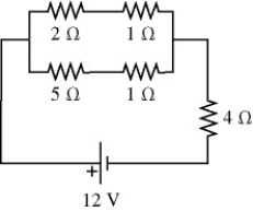
A) 5.33 W
B) 8.0 W
C) 6.67 W
D) 2.67 W
E) 3.56 W
A) 5.33 W
B) 8.0 W
C) 6.67 W
D) 2.67 W
E) 3.56 W
Question
For the circuit shown in the figure, I = 0.50 A and R = 12 Ω. What is the value of the emf ε? 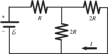
A) 18 V
B) 24 V
C) 6.0 V
D) 12 V
E) 48 V
A) 18 V
B) 24 V
C) 6.0 V
D) 12 V
E) 48 V
Question
Question
For the circuit shown in the figure, the switch S is initially open and the capacitor is uncharged. The switch is then closed at time t = 0. How many seconds after closing the switch will the energy stored in the capacitor be equal to 50.2 mJ? 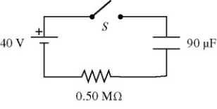
A) 81 s
B) 65 s
C) 97 s
D) 110 s
E) 130 s
A) 81 s
B) 65 s
C) 97 s
D) 110 s
E) 130 s
Question
For the circuit shown in the figure, the switch S is initially open and the capacitor voltage is 80 V. The switch is then closed at time t = 0. How long after closing the switch will the current in the resistor be 7.0 µA? 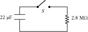
A) 87 s
B) 95 s
C) 78 s
D) 69 s
E) 61 s
A) 87 s
B) 95 s
C) 78 s
D) 69 s
E) 61 s
Question
Question
Question
Question
Question
Question
Question
Question
Question
In the circuit shown in the figure, two 360.0-Ω resistors are connected in series with an ideal source of emf. A voltmeter with internal resistance of 6350 Ω is connected across one of the resistors and reads 3.23 V. Find the emf of the source. 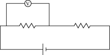
Question
Question
For the circuit shown in the figure, the switch S is initially open and the capacitor voltage is 80 V. The switch is then closed at time t = 0. What is the charge on the capacitor when the current in the circuit is 33 μA? 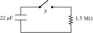
A) 1100 µC
B) 1000 µC
C) 960 µC
D) 890 µC
E) 830 µC
A) 1100 µC
B) 1000 µC
C) 960 µC
D) 890 µC
E) 830 µC
Question
Question
Question
Question
Question
Question
Question
The emf and the internal resistance of a battery are shown in the figure. If a current of 7.8 A is established through the battery from b to a, what is the terminal voltage Vab of the battery? 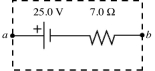
A) -30 V
B) 80 V
C) 30 V
D) -80 V
E) zero
A) -30 V
B) 80 V
C) 30 V
D) -80 V
E) zero
Question
In the figure a current of 6.0 A is drawn from the battery. What is the terminal voltage Vab of the battery? 
A) 0.00 V
B) +12 V
C) +24 V
D) -12 V
E) -24 V
A) 0.00 V
B) +12 V
C) +24 V
D) -12 V
E) -24 V
Question
The emf and the internal resistance of a battery are as shown in the figure. If a current of 8.3 A is drawn from the battery when a resistor R is connected across the terminals ab of the battery, what is the power dissipated by the resistor R? 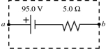
A) 440 W
B) 700 W
C) 620 W
D) 530 W
E) 790 W
A) 440 W
B) 700 W
C) 620 W
D) 530 W
E) 790 W
Question
Question
Question
The emf and the internal resistance of a battery are as shown in the figure. When the terminal voltage Vab is equal to 17.4 V, what is the current through the battery, including its direction? 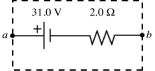
A) 6.8 A, from b to a
B) 8.7 A, from b to a
C) 6.8 A, from a to b
D) 8.7 A, from a to b
E) 16 A, from b to a
A) 6.8 A, from b to a
B) 8.7 A, from b to a
C) 6.8 A, from a to b
D) 8.7 A, from a to b
E) 16 A, from b to a
Question
In the figure, when the terminal voltage Vab of the battery is equal to 20 V, how much current passes through the battery, including its direction? 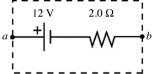
A) 4 A, from a to b
B) 5 A, from a to b
C) 6 A, from a to b
D) 4 A, from b to a
E) 5 A, from b to a
A) 4 A, from a to b
B) 5 A, from a to b
C) 6 A, from a to b
D) 4 A, from b to a
E) 5 A, from b to a
Question

Unlock Deck
Sign up to unlock the cards in this deck!
Unlock Deck
Unlock Deck
1/68
Play
Full screen (f)
Deck 31: Fundamentals of Circuits
1
Two unknown resistors are connected together. When they are connected in series their equivalent resistance is 15 Ω. When they are connected in parallel, their equivalent resistance is 3.3 Ω. What are the resistances of these resistors?
4.9 Ω and 10 Ω
2
A 5.0-Ω resistor and a 9.0-Ω resistor are connected in parallel. A 4.0-Ω resistor is then connected in series with this parallel combination. An ideal 6.0-V battery is then connected across the series-parallel combination of the three resistors. What is the current through
(a) the 4.0-Ω resistor?
(b) the 5.0-Ω resistor?
(c) the 9.0-Ω resistor?
(a) the 4.0-Ω resistor?
(b) the 5.0-Ω resistor?
(c) the 9.0-Ω resistor?
(a) 0.83 A
(b) 0.53 A
(c)0.30 A
(b) 0.53 A
(c)0.30 A
3
Three resistors having resistances of 4.0 Ω, 6.0 Ω, and 10.0 Ω are connected in parallel. If the combination is connected in series with an ideal 12-V battery and a 2.0-Ω resistor, what is the current through the 10.0-Ω resistor?
A) 0.59 A
B) 2.7 A
C) 6.4 A
D) 11.2 A
E) 16 A
A) 0.59 A
B) 2.7 A
C) 6.4 A
D) 11.2 A
E) 16 A
0.59 A
4
In the circuit shown in the figure, an ideal ohmmeter is connected across ab with the switch S open. All the connecting leads have negligible resistance. The reading of the ohmmeter will be closest to
A) 7.5 Ω.
B) 10 Ω.
C) 30 Ω.
D) 40 Ω.
E) 60 Ω.
A) 7.5 Ω.
B) 10 Ω.
C) 30 Ω.
D) 40 Ω.
E) 60 Ω.
Unlock Deck
Unlock for access to all 68 flashcards in this deck.
Unlock Deck
k this deck
5
Four resistors are connected across an 8-V DC battery as shown in the figure. The current through the 9-Ω resistor is closest to
A) 1 A.
B) 0.7 A.
C) 0.5 A.
D) 0.9 A.
E) 2 A.
A) 1 A.
B) 0.7 A.
C) 0.5 A.
D) 0.9 A.
E) 2 A.
Unlock Deck
Unlock for access to all 68 flashcards in this deck.
Unlock Deck
k this deck
6
Two light bulbs, B1 and B2, are connected to a battery having appreciable internal resistance as shown in the figure. What happens to the brightness of bulb B1 when we close the switch S?
A) The brightness of B1 increases permanently.
B) The brightness of B1 decreases permanently.
C) The brightness of B1 does not change.
D) The brightness of B1 increases temporarily but gradually decreases back to its original brightness.
E) The brightness of B1 decreases temporarily but gradually increases back to its original brightness.
Unlock Deck
Unlock for access to all 68 flashcards in this deck.
Unlock Deck
k this deck
7
Three resistors are connected across an ideal 2.0-V DC battery as shown in the figure.
(a) At what rate does the battery supply energy to the resistors?
(b) At what rate is heat produced in the 6.0-Ω resistor?
(a) At what rate does the battery supply energy to the resistors?
(b) At what rate is heat produced in the 6.0-Ω resistor?
Unlock Deck
Unlock for access to all 68 flashcards in this deck.
Unlock Deck
k this deck
8
Thirteen resistors are connected across points A and B as shown in the figure. If all the resistors are accurate to 2 significant figures, what is the equivalent resistance between points A and B?
A) 4.0 Ω
B) 6.0 Ω
C) 8.0 Ω
D) 10 Ω
E) 12 Ω
A) 4.0 Ω
B) 6.0 Ω
C) 8.0 Ω
D) 10 Ω
E) 12 Ω
Unlock Deck
Unlock for access to all 68 flashcards in this deck.
Unlock Deck
k this deck
9
In the circuit shown in the figure, all the lightbulbs are identical. Which of the following is the correct ranking of the brightness of the bulbs?
A) B and C have equal brightness, and A is the dimmest.
B) A and B have equal brightness, and C is the dimmest.
C) A is brightest, C is dimmest, and B is in between.
D) A is the brightest, and B and C have equal brightness but less than A.
E) All three bulbs have the same brightness.
A) B and C have equal brightness, and A is the dimmest.
B) A and B have equal brightness, and C is the dimmest.
C) A is brightest, C is dimmest, and B is in between.
D) A is the brightest, and B and C have equal brightness but less than A.
E) All three bulbs have the same brightness.
Unlock Deck
Unlock for access to all 68 flashcards in this deck.
Unlock Deck
k this deck
10
An RC circuit is connected across an ideal DC voltage source through an open switch. The switch is closed at time t = 0 s. Which of the following statements regarding the circuit are correct? (There may be more than one correct choice.)
A) The capacitor charges to its maximum value in one time constant and the current is zero at that time.
B) The potential difference across the resistor and the potential difference across the capacitor are always equal.
C) The potential difference across the resistor is always greater than the potential difference across the capacitor.
D) The potential difference across the capacitor is always greater than the potential difference across the resistor
E) Once the capacitor is essentially fully charged, there is no appreciable current in the circuit.
Unlock Deck
Unlock for access to all 68 flashcards in this deck.
Unlock Deck
k this deck
11
A galvanometer G has an internal resistance rg. A VOLTMETER is constructed by incorporating the galvanometer and an additional resistance Rs. Which one of the figures below is the most appropriate circuit diagram for the voltmeter?
A) 1
B) 2
C) 3
D) 4
E) 5
A) 1
B) 2
C) 3
D) 4
E) 5
Unlock Deck
Unlock for access to all 68 flashcards in this deck.
Unlock Deck
k this deck
12
A light bulb is connected in the circuit shown in the figure with the switch S open and the capacitor uncharged. The battery has no appreciable internal resistance. Which one of the following graphs best describes the brightness B of the bulb as a function of time t after closing the switch?
A) 1
B) 2
C) 3
D) 4
E) 5
A) 1
B) 2
C) 3
D) 4
E) 5
Unlock Deck
Unlock for access to all 68 flashcards in this deck.
Unlock Deck
k this deck
13
A light bulb is connected in the circuit shown in the figure with the switch S open. All the connecting leads have no appreciable resistance and the battery has no internal resistance. When we close the switch, which statements below accurately describe the behavior of the circuit? (There may be more than one correct choice.)
A) The brightness of the bulb will increase.
B) The brightness of the bulb will decrease.
C) The brightness of the bulb will not change.
D) The potential drop across R2 will decrease.
E) The potential drop across R2 will not change.
A) The brightness of the bulb will increase.
B) The brightness of the bulb will decrease.
C) The brightness of the bulb will not change.
D) The potential drop across R2 will decrease.
E) The potential drop across R2 will not change.
Unlock Deck
Unlock for access to all 68 flashcards in this deck.
Unlock Deck
k this deck
14
The figure shows three identical lightbulbs connected to a battery having a constant voltage across its terminals. What happens to the brightness of lightbulb 1 when the switch S is closed?
A) The brightness will increase momentarily then return to its previous level.
B) The brightness increases permanently.
C) The brightness will decrease momentarily then return to its previous level.
D) The brightness remains the same as before the switch is closed.
E) The brightness decreases permanently.
Unlock Deck
Unlock for access to all 68 flashcards in this deck.
Unlock Deck
k this deck
15
For the circuit shown in the figure, determine the current in
(a) the 1.0-Ω resistor.
(b) the 3.0-Ω resistor.
(c) the 4.0-Ω resistor.
(a) the 1.0-Ω resistor.
(b) the 3.0-Ω resistor.
(c) the 4.0-Ω resistor.
Unlock Deck
Unlock for access to all 68 flashcards in this deck.
Unlock Deck
k this deck
16
A resistor is made out of a long wire having a length L. Each end of the wire is attached to a terminal of a battery providing a constant voltage V0. A current I flows through the wire. If the wire were cut in half, making two wires of length L/2, and both wires were attached to the battery (the end of both wires attached to one terminal, and the other ends attached to the other terminal), what would be the total current flowing through the two wires?
A) 4I
B) 2I
C) I
D) I/2
E) I/4
A) 4I
B) 2I
C) I
D) I/2
E) I/4
Unlock Deck
Unlock for access to all 68 flashcards in this deck.
Unlock Deck
k this deck
17
A galvanometer G has an internal resistance rg. An AMMETER is constructed by incorporating the galvanometer and an additional resistance Rs. Which one of the figures below is the most appropriate circuit diagram for the ammeter?
A) 1
B) 2
C) 3
D) 4
E) 5
A) 1
B) 2
C) 3
D) 4
E) 5
Unlock Deck
Unlock for access to all 68 flashcards in this deck.
Unlock Deck
k this deck
18
As more resistors are added in parallel across a constant voltage source, the power supplied by the source
A) increases.
B) decreases.
C) does not change.
A) increases.
B) decreases.
C) does not change.
Unlock Deck
Unlock for access to all 68 flashcards in this deck.
Unlock Deck
k this deck
19
A 4.00-Ω resistor, an 8.00-Ω resistor, and a 24.0-Ω resistor are connected together.
(a) What is the maximum resistance that can be produced using all three resistors?
(b) What is the minimum resistance that can be produced using all three resistors?
(c) How would you connect these three resistors to obtain a resistance of 10.0 Ω?
(d) How would you connect these three resistors to obtain a resistance of 8.00 Ω?
Unlock Deck
Unlock for access to all 68 flashcards in this deck.
Unlock Deck
k this deck
20
In the circuit shown in the figure, four identical resistors labeled A to D are connected to a battery as shown. S1 and S2 are switches. Which of the following actions would result in the GREATEST amount of current through resistor A?
A) closing both switches
B) closing S1 only
C) closing S2 only
D) leaving both switches open as shown.
A) closing both switches
B) closing S1 only
C) closing S2 only
D) leaving both switches open as shown.
Unlock Deck
Unlock for access to all 68 flashcards in this deck.
Unlock Deck
k this deck
21
For the circuit shown in the figure, what current does the ideal ammeter read?
A) 0.033 A
B) 0.078 A
C) 0.23 A
D) 0.12 A
A) 0.033 A
B) 0.078 A
C) 0.23 A
D) 0.12 A
Unlock Deck
Unlock for access to all 68 flashcards in this deck.
Unlock Deck
k this deck
22
When a 20.0-ohm resistor is connected across the terminals of a 12.0-V battery, the voltage across the terminals of the battery falls by 0.300 V. What is the internal resistance of this battery?
A) 3.60 Ω
B) 1.56 Ω
C) 0.98 Ω
D) 0.30 Ω
E) 0.51 Ω
A) 3.60 Ω
B) 1.56 Ω
C) 0.98 Ω
D) 0.30 Ω
E) 0.51 Ω
Unlock Deck
Unlock for access to all 68 flashcards in this deck.
Unlock Deck
k this deck
23
For the circuit shown in the figure, all quantities are accurate to 2 significant figures. What is the value of the current I1?
A) 0.32 A
B) 0.11 A
C) 0.29 A
D) 0.61 A
E) 0.89 A
A) 0.32 A
B) 0.11 A
C) 0.29 A
D) 0.61 A
E) 0.89 A
Unlock Deck
Unlock for access to all 68 flashcards in this deck.
Unlock Deck
k this deck
24
When four identical resistors are connected to an ideal battery of voltage V = 10 V as shown in the figure, the current I is equal to 0.20 A. What is the value of the resistance R of the resistors?
A) 20 Ω
B) 40 Ω
C) 30 Ω
D) 50 Ω
E) 10 Ω
A) 20 Ω
B) 40 Ω
C) 30 Ω
D) 50 Ω
E) 10 Ω
Unlock Deck
Unlock for access to all 68 flashcards in this deck.
Unlock Deck
k this deck
25
For the circuit shown in the figure, the current in the 8-Ω resistor is 0.50 A, and all quantities are accurate to 2 significant figures. What is the current in the 2-Ω resistor?
A) 2.25 A
B) 0.75 A
C) 4.5 A
D) 9.5 A
E) 6.4 A
A) 2.25 A
B) 0.75 A
C) 4.5 A
D) 9.5 A
E) 6.4 A
Unlock Deck
Unlock for access to all 68 flashcards in this deck.
Unlock Deck
k this deck
26
When a 100-Ω resistor is connected across the terminals of a battery of emf ε and internal resistance r, the battery delivers 0.794 W of power to the 100-Ω resistor. When the 100-Ω resistor is replaced by a 200-Ω resistor, the battery delivers 0.401 W of power to the 200-Ω resistor. What are the emf and internal resistance of the battery?
A) ε = 10.0 V, r = 5.02 Ω
B) ε = 4.50 V, r = 4.00 Ω
C) ε = 9.00 V, r = 2.04 Ω
D) ε = 9.00 V, r = 1.01 Ω
E) ε = 12.0 V, r = 6.00 Ω
A) ε = 10.0 V, r = 5.02 Ω
B) ε = 4.50 V, r = 4.00 Ω
C) ε = 9.00 V, r = 2.04 Ω
D) ε = 9.00 V, r = 1.01 Ω
E) ε = 12.0 V, r = 6.00 Ω
Unlock Deck
Unlock for access to all 68 flashcards in this deck.
Unlock Deck
k this deck
27
Consider the circuit shown in the figure. Note that two currents are shown. Calculate the emfs ε1 and ε3.
Unlock Deck
Unlock for access to all 68 flashcards in this deck.
Unlock Deck
k this deck
28
A multiloop circuit is shown in the figure. Some circuit quantities are not labeled. It is not necessary to solve the entire circuit. The current I2 is closest to
A) +0.1 A.
B) +0.3 A.
C) +0.5 A.
D) -0.1 A.
E) -0.3 A.
A) +0.1 A.
B) +0.3 A.
C) +0.5 A.
D) -0.1 A.
E) -0.3 A.
Unlock Deck
Unlock for access to all 68 flashcards in this deck.
Unlock Deck
k this deck
29
A multiloop circuit is shown in the figure. Some circuit quantities are not labeled. It is not necessary to solve the entire circuit. The current I1 is closest to
A) zero.
B) +0.2 A.
C) +0.4 A.
D) -0.2 A.
E) -0.4 A.
A) zero.
B) +0.2 A.
C) +0.4 A.
D) -0.2 A.
E) -0.4 A.
Unlock Deck
Unlock for access to all 68 flashcards in this deck.
Unlock Deck
k this deck
30
A multiloop circuit is shown in the figure. Some circuit quantities are not labeled. It is not necessary to solve the entire circuit. The emf ε is closest to
A) +3 V.
B) +19 V.
C) -3 V.
D) -10 V.
E) -1 V.
A) +3 V.
B) +19 V.
C) -3 V.
D) -10 V.
E) -1 V.
Unlock Deck
Unlock for access to all 68 flashcards in this deck.
Unlock Deck
k this deck
31
What is the maximum current that can be drawn from a 1.50-V battery with an internal resistance of 0.30 ohm?
A) 2.5 A
B) 5.0 A
C) 0.45 A
D) 0.20 A
E) 4.5 A
A) 2.5 A
B) 5.0 A
C) 0.45 A
D) 0.20 A
E) 4.5 A
Unlock Deck
Unlock for access to all 68 flashcards in this deck.
Unlock Deck
k this deck
32
For the circuit shown in the figure, what is the current through resistor R3?
A) 0.043 A
B) 1.5 A
C) 0.028 A
D) 0.086 A
A) 0.043 A
B) 1.5 A
C) 0.028 A
D) 0.086 A
Unlock Deck
Unlock for access to all 68 flashcards in this deck.
Unlock Deck
k this deck
33
Two identical resistors of resistance R = 24 Ω and a variable resistor Rx are connected to an ideal battery of voltage V as shown in the figure. What should be the value of the variable resistance Rx to make the voltage across the two parallel resistors equal to .
A) 4.0 Ω
B) 24 Ω
C) 8.0 Ω
D) 16 Ω
E) 40 Ω
. A) 4.0 Ω
B) 24 Ω
C) 8.0 Ω
D) 16 Ω
E) 40 Ω
Unlock Deck
Unlock for access to all 68 flashcards in this deck.
Unlock Deck
k this deck
34
For the circuit shown in the figure, what is the current through resistor R1?
A) 0.071 A
B) 0.13 A
C) 0.029 A
D) 0.016 A
A) 0.071 A
B) 0.13 A
C) 0.029 A
D) 0.016 A
Unlock Deck
Unlock for access to all 68 flashcards in this deck.
Unlock Deck
k this deck
35
A multiloop circuit is shown in the figure. It is not necessary to solve the entire circuit. The current I2 is closest to
A) -6 A.
B) 6 A.
C) 8 A.
D) -8 A.
E) zero.
A) -6 A.
B) 6 A.
C) 8 A.
D) -8 A.
E) zero.
Unlock Deck
Unlock for access to all 68 flashcards in this deck.
Unlock Deck
k this deck
36
A galvanometer coil having a resistance of 20 Ω and a full-scale deflection at 1.0 mA is connected in series with a 4980 Ω resistance to build a voltmeter. What is the maximum voltage that this voltmeter can read?
A) 3.0 V
B) 1.0 V
C) 50 V
D) 5.0 V
E) 10 V
A) 3.0 V
B) 1.0 V
C) 50 V
D) 5.0 V
E) 10 V
Unlock Deck
Unlock for access to all 68 flashcards in this deck.
Unlock Deck
k this deck
37
For the circuit shown in the figure, determine the current in
(a) the 7.0-Ω resistor.
(b) the 8.0-Ω resistor.
(c) the 4.0-Ω resistor.
(a) the 7.0-Ω resistor.
(b) the 8.0-Ω resistor.
(c) the 4.0-Ω resistor.
Unlock Deck
Unlock for access to all 68 flashcards in this deck.
Unlock Deck
k this deck
38
A multiloop circuit is shown in the figure. It is not necessary to solve the entire circuit. Compared to the polarity shown in the figure, the emf ε1 is closest to
A) -5 V.
B) 5 V.
C) 45 V.
D) 51 V.
E) -51 V.
A) -5 V.
B) 5 V.
C) 45 V.
D) 51 V.
E) -51 V.
Unlock Deck
Unlock for access to all 68 flashcards in this deck.
Unlock Deck
k this deck
39
For the circuit shown in the figure, all quantities are accurate to 3 significant figures. What is the power dissipated in the 2-Ω resistor?
A) 5.33 W
B) 8.0 W
C) 6.67 W
D) 2.67 W
E) 3.56 W
A) 5.33 W
B) 8.0 W
C) 6.67 W
D) 2.67 W
E) 3.56 W
Unlock Deck
Unlock for access to all 68 flashcards in this deck.
Unlock Deck
k this deck
40
For the circuit shown in the figure, I = 0.50 A and R = 12 Ω. What is the value of the emf ε?
A) 18 V
B) 24 V
C) 6.0 V
D) 12 V
E) 48 V
A) 18 V
B) 24 V
C) 6.0 V
D) 12 V
E) 48 V
Unlock Deck
Unlock for access to all 68 flashcards in this deck.
Unlock Deck
k this deck
41
A 1500-W heater is connected to a 120-V line. How much heat energy does it produce in 2.0 hours?
A) 1.5 kJ
B) 3.0 kJ
C) 0.18 MJ
D) 11 MJ
E) 18 MJ
A) 1.5 kJ
B) 3.0 kJ
C) 0.18 MJ
D) 11 MJ
E) 18 MJ
Unlock Deck
Unlock for access to all 68 flashcards in this deck.
Unlock Deck
k this deck
42
For the circuit shown in the figure, the switch S is initially open and the capacitor is uncharged. The switch is then closed at time t = 0. How many seconds after closing the switch will the energy stored in the capacitor be equal to 50.2 mJ?
A) 81 s
B) 65 s
C) 97 s
D) 110 s
E) 130 s
A) 81 s
B) 65 s
C) 97 s
D) 110 s
E) 130 s
Unlock Deck
Unlock for access to all 68 flashcards in this deck.
Unlock Deck
k this deck
43
For the circuit shown in the figure, the switch S is initially open and the capacitor voltage is 80 V. The switch is then closed at time t = 0. How long after closing the switch will the current in the resistor be 7.0 µA?
A) 87 s
B) 95 s
C) 78 s
D) 69 s
E) 61 s
A) 87 s
B) 95 s
C) 78 s
D) 69 s
E) 61 s
Unlock Deck
Unlock for access to all 68 flashcards in this deck.
Unlock Deck
k this deck
44
The resistivity of gold is 2.44 × 10⁻⁸ Ω ∙ m at room temperature. A gold wire that is 1.8 mm in diameter and 11 cm long carries a current of 170 mA. How much power is dissipated in the wire?
A) 0.030 mW
B) 0.0076 mW
C) 0.013 mW
D) 0.019 mW
E) 0.025 mW
A) 0.030 mW
B) 0.0076 mW
C) 0.013 mW
D) 0.019 mW
E) 0.025 mW
Unlock Deck
Unlock for access to all 68 flashcards in this deck.
Unlock Deck
k this deck
45
An uncharged 30.0-µF capacitor is connected in series with a 25.0-Ω resistor, a DC battery, and an open switch. The battery has an internal resistance of 10.0 Ω and the open-circuit voltage across its terminals is 50.0 V. The leads have no appreciable resistance. At time t = 0, the switch is suddenly closed.
(a) What is the maximum current through the 25.0-Ω resistor and when does it occur (immediately after closing the switch or after the switch has been closed for a long time)?
(b) What is the maximum charge that the capacitor receives?
(c) When the current in the circuit is 0.850 A, how much charge is on the plates of the capacitor?
Unlock Deck
Unlock for access to all 68 flashcards in this deck.
Unlock Deck
k this deck
46
A 4.0-μF capacitor that is initially uncharged is connected in series with a 4.0-kΩ resistor and an ideal 17.0-V battery. How much energy is stored in the capacitor 17 ms after the battery has been connected?
A) 250,000 nJ
B) 15,000 kJ
C) 25 µJ
D) 890 nJ
A) 250,000 nJ
B) 15,000 kJ
C) 25 µJ
D) 890 nJ
Unlock Deck
Unlock for access to all 68 flashcards in this deck.
Unlock Deck
k this deck
47
A galvanometer with a resistance of 40.0 Ω deflects full scale at a current of 2.0 mA. What resistance should be used with this galvanometer in order to construct a voltmeter that can read a maximum of 50 V?
A) 25 kΩ
B) 27 kΩ
C) 29 kΩ
D) 31 kΩ
E) 35 kΩ
A) 25 kΩ
B) 27 kΩ
C) 29 kΩ
D) 31 kΩ
E) 35 kΩ
Unlock Deck
Unlock for access to all 68 flashcards in this deck.
Unlock Deck
k this deck
48
A 6.0-μF capacitor is connected in series with= 5.0 MΩ resistor, and this combination is connected across an ideal 15-V DC battery. What is the current in the circuit when the capacitor has reached 20% of its maximum charge?
A) 6.5 μA
B) 2.4 μA
C) 1.3 μA
D) 4.7 μA
E) 9.1 μA
A) 6.5 μA
B) 2.4 μA
C) 1.3 μA
D) 4.7 μA
E) 9.1 μA
Unlock Deck
Unlock for access to all 68 flashcards in this deck.
Unlock Deck
k this deck
49
A certain electric furnace consumes 24 kW when it is connected to a 240-V line. What is the resistance of the furnace?
A) 1.0 kΩ
B) 10 Ω
C) 2.4 Ω
D) 0.42 Ω
E) 100 Ω
A) 1.0 kΩ
B) 10 Ω
C) 2.4 Ω
D) 0.42 Ω
E) 100 Ω
Unlock Deck
Unlock for access to all 68 flashcards in this deck.
Unlock Deck
k this deck
50
A 400-W computer (including the monitor) is turned on for 8.0 hours per day. If electricity costs 10¢ per kWh, how much does it cost to run the computer annually for a typical 365-day year?
A) $120
B) $1200
C) $15
D) $17
E) $150
A) $120
B) $1200
C) $15
D) $17
E) $150
Unlock Deck
Unlock for access to all 68 flashcards in this deck.
Unlock Deck
k this deck
51
A light bulb is connected to a 110-V source. What is the resistance of this bulb if it is a 100-W bulb?
A) 100 Ω
B) 8.0 mΩ
C) 6.0 mΩ
D) 120 Ω
E) 240 Ω
A) 100 Ω
B) 8.0 mΩ
C) 6.0 mΩ
D) 120 Ω
E) 240 Ω
Unlock Deck
Unlock for access to all 68 flashcards in this deck.
Unlock Deck
k this deck
52
In the circuit shown in the figure, two 360.0-Ω resistors are connected in series with an ideal source of emf. A voltmeter with internal resistance of 6350 Ω is connected across one of the resistors and reads 3.23 V. Find the emf of the source.
Unlock Deck
Unlock for access to all 68 flashcards in this deck.
Unlock Deck
k this deck
53
A galvanometer has a coil with a resistance of 24.0 Ω, and a current of 180 μA causes it to deflect full scale. If this galvanometer is to be used to construct an ammeter that can read up to 10.0 A, what shunt resistor is required?
A) 123 µΩ
B) 234 µΩ
C) 342 µΩ
D) 432 µΩ
E) 423 µΩ
A) 123 µΩ
B) 234 µΩ
C) 342 µΩ
D) 432 µΩ
E) 423 µΩ
Unlock Deck
Unlock for access to all 68 flashcards in this deck.
Unlock Deck
k this deck
54
For the circuit shown in the figure, the switch S is initially open and the capacitor voltage is 80 V. The switch is then closed at time t = 0. What is the charge on the capacitor when the current in the circuit is 33 μA?
A) 1100 µC
B) 1000 µC
C) 960 µC
D) 890 µC
E) 830 µC
A) 1100 µC
B) 1000 µC
C) 960 µC
D) 890 µC
E) 830 µC
Unlock Deck
Unlock for access to all 68 flashcards in this deck.
Unlock Deck
k this deck
55
A 4.0-mF capacitor is discharged through a 4.0-kΩ resistor. How long will it take for the capacitor to lose half its initial stored energy?
A) 9.2 s
B) 2.7 s
C) 10.2 s
D) 5.5 s
E) 1.6 s
A) 9.2 s
B) 2.7 s
C) 10.2 s
D) 5.5 s
E) 1.6 s
Unlock Deck
Unlock for access to all 68 flashcards in this deck.
Unlock Deck
k this deck
56
A galvanometer has an internal resistance of 100 Ω and deflects full-scale at 2.00 mA. What size resistor should be added to the galvanometer to convert it to a milliammeter capable of reading up to 4.00 mA, and how should this resistor be connected to the galvanometer?
A) 50.0 Ω in series with the galvanometer
B) 50.0 Ω in parallel with the galvanometer
C) 75.0 Ω in parallel with the galvanometer
D) 100 Ω in series with the galvanometer
E) 100 Ω in parallel with the galvanometer
A) 50.0 Ω in series with the galvanometer
B) 50.0 Ω in parallel with the galvanometer
C) 75.0 Ω in parallel with the galvanometer
D) 100 Ω in series with the galvanometer
E) 100 Ω in parallel with the galvanometer
Unlock Deck
Unlock for access to all 68 flashcards in this deck.
Unlock Deck
k this deck
57
A 110-V hair dryer is rated at 1200 W. What current will it draw when operating from a 110-V electrical outlet?
A) 90 mA
B) 1.0 A
C) 5.0 A
D) 11 A
E) 14 A
A) 90 mA
B) 1.0 A
C) 5.0 A
D) 11 A
E) 14 A
Unlock Deck
Unlock for access to all 68 flashcards in this deck.
Unlock Deck
k this deck
58
The power rating of a 400-Ω resistor is 0.800 W.
(a) What is the maximum voltage that can be applied across this resistor without damaging it?
(b) What is the maximum current this resistor can draw without damaging it?
(a) What is the maximum voltage that can be applied across this resistor without damaging it?
(b) What is the maximum current this resistor can draw without damaging it?
Unlock Deck
Unlock for access to all 68 flashcards in this deck.
Unlock Deck
k this deck
59
An uncharged 1.0-μF capacitor is connected in series with a 23-kΩ resistor, an ideal 7.0-V battery, and an open switch. What is the voltage across the capacitor 11 ms after closing the switch?
A) 2.7 V
B) 1.6 V
C) 2.6 V
D) 0.62 V
A) 2.7 V
B) 1.6 V
C) 2.6 V
D) 0.62 V
Unlock Deck
Unlock for access to all 68 flashcards in this deck.
Unlock Deck
k this deck
60
A galvanometer has an internal resistance of 100 Ω and deflects full-scale at a current of 2.00 mA. What size resistor should be added to it to convert it to a millivoltmeter capable of reading up to 400 mV, and how should this resistor be connected to the galvanometer?
A) 50.0 Ω in series with the galvanometer
B) 50.0 Ω in parallel with the galvanometer
C) 75.0 Ω in parallel with the galvanometer
D) 100 Ω in series with the galvanometer
E) 100 Ω in parallel with the galvanometer
A) 50.0 Ω in series with the galvanometer
B) 50.0 Ω in parallel with the galvanometer
C) 75.0 Ω in parallel with the galvanometer
D) 100 Ω in series with the galvanometer
E) 100 Ω in parallel with the galvanometer
Unlock Deck
Unlock for access to all 68 flashcards in this deck.
Unlock Deck
k this deck
61
The emf and the internal resistance of a battery are shown in the figure. If a current of 7.8 A is established through the battery from b to a, what is the terminal voltage Vab of the battery?
A) -30 V
B) 80 V
C) 30 V
D) -80 V
E) zero
A) -30 V
B) 80 V
C) 30 V
D) -80 V
E) zero
Unlock Deck
Unlock for access to all 68 flashcards in this deck.
Unlock Deck
k this deck
62
In the figure a current of 6.0 A is drawn from the battery. What is the terminal voltage Vab of the battery?
A) 0.00 V
B) +12 V
C) +24 V
D) -12 V
E) -24 V
A) 0.00 V
B) +12 V
C) +24 V
D) -12 V
E) -24 V
Unlock Deck
Unlock for access to all 68 flashcards in this deck.
Unlock Deck
k this deck
63
The emf and the internal resistance of a battery are as shown in the figure. If a current of 8.3 A is drawn from the battery when a resistor R is connected across the terminals ab of the battery, what is the power dissipated by the resistor R?
A) 440 W
B) 700 W
C) 620 W
D) 530 W
E) 790 W
A) 440 W
B) 700 W
C) 620 W
D) 530 W
E) 790 W
Unlock Deck
Unlock for access to all 68 flashcards in this deck.
Unlock Deck
k this deck
64
The voltage and power ratings of a particular light bulb, which are its normal operating values, are 110 V and 60 W. Assume the resistance of the filament of the bulb is constant and is independent of operating conditions. If the light bulb is operated with a current that is 50% of the current rating of the bulb, what is the actual power drawn by the bulb?
A) 10 W
B) 15 W
C) 20 W
D) 25 W
E) 30 W
A) 10 W
B) 15 W
C) 20 W
D) 25 W
E) 30 W
Unlock Deck
Unlock for access to all 68 flashcards in this deck.
Unlock Deck
k this deck
65
The voltage and power ratings of a particular light bulb, which are its normal operating values, are 110 V and 60 W. Assume the resistance of the filament of the bulb is constant and is independent of operating conditions. If the light bulb is operated at a reduced voltage and the power drawn by the bulb is 36 W, what is the operating voltage of the bulb?
A) 66 V
B) 72 V
C) 78 V
D) 85 V
E) 90 V
A) 66 V
B) 72 V
C) 78 V
D) 85 V
E) 90 V
Unlock Deck
Unlock for access to all 68 flashcards in this deck.
Unlock Deck
k this deck
66
The emf and the internal resistance of a battery are as shown in the figure. When the terminal voltage Vab is equal to 17.4 V, what is the current through the battery, including its direction?
A) 6.8 A, from b to a
B) 8.7 A, from b to a
C) 6.8 A, from a to b
D) 8.7 A, from a to b
E) 16 A, from b to a
A) 6.8 A, from b to a
B) 8.7 A, from b to a
C) 6.8 A, from a to b
D) 8.7 A, from a to b
E) 16 A, from b to a
Unlock Deck
Unlock for access to all 68 flashcards in this deck.
Unlock Deck
k this deck
67
In the figure, when the terminal voltage Vab of the battery is equal to 20 V, how much current passes through the battery, including its direction?
A) 4 A, from a to b
B) 5 A, from a to b
C) 6 A, from a to b
D) 4 A, from b to a
E) 5 A, from b to a
A) 4 A, from a to b
B) 5 A, from a to b
C) 6 A, from a to b
D) 4 A, from b to a
E) 5 A, from b to a
Unlock Deck
Unlock for access to all 68 flashcards in this deck.
Unlock Deck
k this deck
68
The heater element of a particular 120-V toaster is a 8.9-m length of nichrome wire, whose diameter is 0.86 mm. The resistivity of nichrome at the operating temperature of the toaster is 1.3 × 10⁻⁶ Ω ∙ m. If the toaster is operated at a voltage of 120 V, how much power does it draw?
A) 720 W
B) 700 W
C) 750 W
D) 770 W
E) 800 W
A) 720 W
B) 700 W
C) 750 W
D) 770 W
E) 800 W
Unlock Deck
Unlock for access to all 68 flashcards in this deck.
Unlock Deck
k this deck
Unlock Deck
Unlock for access to all 68 flashcards in this deck.


