Exam 31: Fundamentals of Circuits
Exam 1: Concepts of Motion52 Questions
Exam 2: Kinematics in One Dimension59 Questions
Exam 3: Vectors and Coordinate Systems33 Questions
Exam 4: Kinematics in Two Dimensions50 Questions
Exam 5: Force and Motion31 Questions
Exam 6: Dynamics I: Motion Along a Line46 Questions
Exam 7: Newtons Third Law43 Questions
Exam 8: Dynamics Ii: Motion in a Plane20 Questions
Exam 9: Impulse and Momentum20 Questions
Exam 10: Energy43 Questions
Exam 11: Work100 Questions
Exam 12: Rotation of a Rigid Body113 Questions
Exam 13: Newtons Theory of Gravity50 Questions
Exam 14: Oscillations49 Questions
Exam 15: Fluids and Elasticity72 Questions
Exam 16: A Macroscopic Description of Matter29 Questions
Exam 17: Work, Heat, and the First Law of Thermodynamics98 Questions
Exam 18: The Micromacro Connection39 Questions
Exam 19: Heat Engines and Refrigerators50 Questions
Exam 20: Traveling Waves49 Questions
Exam 21: Superpositions64 Questions
Exam 22: Wave Optics51 Questions
Exam 23: Ray Optics63 Questions
Exam 24: Optical Instruments49 Questions
Exam 25: Electric Charges and Forces26 Questions
Exam 26: The Electric Field32 Questions
Exam 27: Gausss Law41 Questions
Exam 28: The Electric Potential40 Questions
Exam 29: Potential and Field57 Questions
Exam 30: Current and Resistance32 Questions
Exam 31: Fundamentals of Circuits68 Questions
Exam 32: The Magnetic Field87 Questions
Exam 33: Electromagnetic Induction66 Questions
Exam 34: Electromagnetic Fields and Waves52 Questions
Exam 35: Ac Circuits46 Questions
Exam 36: Relativity49 Questions
Exam 37: The Foundations of Modern Physics8 Questions
Exam 38: Quantization54 Questions
Exam 39: Wave Functions and Uncertainty18 Questions
Exam 40: One-Dimensional Quantum Mechanics32 Questions
Exam 41: Atomic Physics39 Questions
Exam 42: Nuclear Physics65 Questions
Select questions type
A 4.0-μF capacitor that is initially uncharged is connected in series with a 4.0-kΩ resistor and an ideal 17.0-V battery. How much energy is stored in the capacitor 17 ms after the battery has been connected?
Free
(Multiple Choice)
4.7/5  (36)
(36)
Correct Answer: Verified
A
A galvanometer coil having a resistance of 20 Ω and a full-scale deflection at 1.0 mA is connected in series with a 4980 Ω resistance to build a voltmeter. What is the maximum voltage that this voltmeter can read?
Free
(Multiple Choice)
4.9/5 (40)
Correct Answer:Verified
D
A 5.0-Ω resistor and a 9.0-Ω resistor are connected in parallel. A 4.0-Ω resistor is then connected in series with this parallel combination. An ideal 6.0-V battery is then connected across the series-parallel combination of the three resistors. What is the current through
(a) the 4.0-Ω resistor?
(b) the 5.0-Ω resistor?
(c) the 9.0-Ω resistor?
Free
(Essay)
4.9/5 (44)
Correct Answer:Verified
(a) 0.83 A
(b) 0.53 A
(c)0.30 A
A 4.0-mF capacitor is discharged through a 4.0-kΩ resistor. How long will it take for the capacitor to lose half its initial stored energy?
(Multiple Choice)
4.8/5 (42)
A 4.00-Ω resistor, an 8.00-Ω resistor, and a 24.0-Ω resistor are connected together.
(a) What is the maximum resistance that can be produced using all three resistors?
(b) What is the minimum resistance that can be produced using all three resistors?
(c) How would you connect these three resistors to obtain a resistance of 10.0 Ω?
(d) How would you connect these three resistors to obtain a resistance of 8.00 Ω?
(Essay)
4.8/5 (33)
In the circuit shown in the figure, two 360.0-Ω resistors are connected in series with an ideal source of emf. A voltmeter with internal resistance of 6350 Ω is connected across one of the resistors and reads 3.23 V. Find the emf of the source. 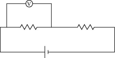
(Short Answer)
4.7/5 (37)
For the circuit shown in the figure, the switch S is initially open and the capacitor is uncharged. The switch is then closed at time t = 0. How many seconds after closing the switch will the energy stored in the capacitor be equal to 50.2 mJ? 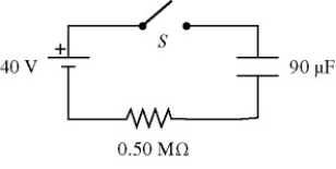
(Multiple Choice)
4.9/5 (28)
The voltage and power ratings of a particular light bulb, which are its normal operating values, are 110 V and 60 W. Assume the resistance of the filament of the bulb is constant and is independent of operating conditions. If the light bulb is operated at a reduced voltage and the power drawn by the bulb is 36 W, what is the operating voltage of the bulb?
(Multiple Choice)
4.7/5 (30)
Two unknown resistors are connected together. When they are connected in series their equivalent resistance is 15 Ω. When they are connected in parallel, their equivalent resistance is 3.3 Ω. What are the resistances of these resistors?
(Short Answer)
4.7/5 (37)
When a 20.0-ohm resistor is connected across the terminals of a 12.0-V battery, the voltage across the terminals of the battery falls by 0.300 V. What is the internal resistance of this battery?
(Multiple Choice)
4.8/5 (32)
An uncharged 30.0-µF capacitor is connected in series with a 25.0-Ω resistor, a DC battery, and an open switch. The battery has an internal resistance of 10.0 Ω and the open-circuit voltage across its terminals is 50.0 V. The leads have no appreciable resistance. At time t = 0, the switch is suddenly closed.
(a) What is the maximum current through the 25.0-Ω resistor and when does it occur (immediately after closing the switch or after the switch has been closed for a long time)?
(b) What is the maximum charge that the capacitor receives?
(c) When the current in the circuit is 0.850 A, how much charge is on the plates of the capacitor?
(Essay)
4.9/5 (38)
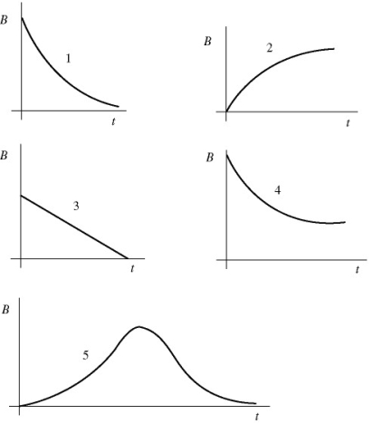
A light bulb is connected in the circuit shown in the figure with the switch S open and the capacitor uncharged. The battery has no appreciable internal resistance. Which one of the following graphs best describes the brightness B of the bulb as a function of time t after closing the switch? 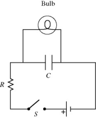
(Multiple Choice)
4.9/5 (33)
For the circuit shown in the figure, the switch S is initially open and the capacitor voltage is 80 V. The switch is then closed at time t = 0. How long after closing the switch will the current in the resistor be 7.0 µA? 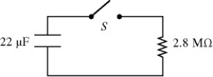
(Multiple Choice)
4.9/5 (33)
For the circuit shown in the figure, what is the current through resistor R3? 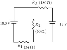
(Multiple Choice)
4.8/5 (38)
The emf and the internal resistance of a battery are as shown in the figure. If a current of 8.3 A is drawn from the battery when a resistor R is connected across the terminals ab of the battery, what is the power dissipated by the resistor R? 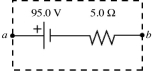
(Multiple Choice)
4.8/5 (37)
A galvanometer has an internal resistance of 100 Ω and deflects full-scale at 2.00 mA. What size resistor should be added to the galvanometer to convert it to a milliammeter capable of reading up to 4.00 mA, and how should this resistor be connected to the galvanometer?
(Multiple Choice)
4.7/5 (44)
The resistivity of gold is 2.44 × 10⁻⁸ Ω ∙ m at room temperature. A gold wire that is 1.8 mm in diameter and 11 cm long carries a current of 170 mA. How much power is dissipated in the wire?
(Multiple Choice)
4.8/5 (31)
For the circuit shown in the figure, what is the current through resistor R1? 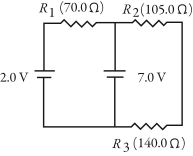
(Multiple Choice)
4.8/5 (40)
An uncharged 1.0-μF capacitor is connected in series with a 23-kΩ resistor, an ideal 7.0-V battery, and an open switch. What is the voltage across the capacitor 11 ms after closing the switch?
(Multiple Choice)
4.8/5 (32)
A light bulb is connected in the circuit shown in the figure with the switch S open. All the connecting leads have no appreciable resistance and the battery has no internal resistance. When we close the switch, which statements below accurately describe the behavior of the circuit? (There may be more than one correct choice.) 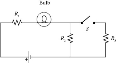
(Multiple Choice)
5.0/5 (39)
Filters
- Essay(0)
- Multiple Choice(0)
- Short Answer(0)
- True False(0)
- Matching(0)