Short Answer
For the circuit shown in the figure, the ideal battery has an emf ? = 80 V. The four resistors have resistances of and Calculate the rate at which heat is being generated in the resistor R4. 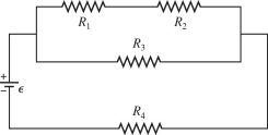
Correct Answer:

Verified
Correct Answer:
Verified
Related Questions
Q63: A 6.0-Ω and a 12-Ω resistor are
Q93: A system of four capacitors is connected
Q98: The network shown is assembled with
Q99: For the circuit shown in the figure,
Q100: The resistors in the circuit shown
Q101: A network of capacitors is connected across
Q102: Three light bulbs, A, B, and C,
Q187: When two or more different capacitors are
Q208: A resistor,an uncharged capacitor,a dc voltage source,and
Q304: You have three capacitors with capacitances of