menu-iconExamlexExamLexServices

Discover

Ask a Question
  1. All Topics
  2. Topic
    Physics & Astronomy
  3. Study Set
    College Physics
  4. Exam
    Exam 23: Circuits
  5. Question
    In the Circuit Shown in the Figure, R<sub>1</sub> = 10
Solved

In the Circuit Shown in the Figure, R1 = 10

Question 144

Question 144

Multiple Choice

In the circuit shown in the figure, R1 = 10 Ω, R2 = 12 Ω, R3 = 20 Ω, V1 = 1.0 V, V2 = 7.0 V, and the batteries are both ideal. What is the current through R1?
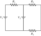
 In the circuit shown in the figure, R<sub>1</sub> = 10 Ω, R<sub>2</sub> = 12 Ω, R<sub>3</sub> = 20 Ω, V<sub>1</sub> = 1.0 V, V<sub>2</sub> = 7.0 V, and the batteries are both ideal. What is the current through R<sub>1</sub>?   A) 0.60 A B) 0.80 A C) 0.18 A D) 0.13 A


A) 0.60 A
B) 0.80 A
C) 0.18 A
D) 0.13 A

Correct Answer:

verifed

Verified

Unlock this answer now
Get Access to more Verified Answers free of charge

Related Questions

Q72: Four resistors having resistances of 20 Ω,40

Q136: Identical ideal batteries are connected in different

Q137: What is the magnitude of the potential

Q139: Kirchhoff's loop rule is a statement of<br>A)the

Q140: For the circuit shown in the figure,

Q142: Four resistors are connected across an ideal

Q143: What is the magnitude of the potential

Q145: A 9-V battery is hooked up to

Q160: A 2.0-μF capacitor is charged to 12

Q200: A resistor,an uncharged capacitor,a dc voltage source,and

Examlex

ExamLex

About UsContact UsPerks CenterHomeschoolingTest Prep

Work With Us

Campus RepresentativeInfluencers

Links

FaqPricingChrome Extension

Download The App

Get App StoreGet Google Play

Policies

Privacy PolicyTerms of ServiceHonor CodeCommunity Guidelines

Scan To Download

qr-code

Copyright © (2025) ExamLex LLC.

Privacy PolicyTerms Of ServiceHonor CodeCommunity Guidelines