Short Answer
For the circuit shown in the figure, R1 = 18 ?, R2 = 44 ?, R3 = 33 ?, R4 = 14 ?, R5 = 12 ?, V1 = 18 V, V2 = 12 V, and the batteries are ideal. Determine I1 and I2. 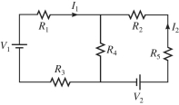
Correct Answer:

Verified
I1 = 0.25 A...View Answer
Unlock this answer now
Get Access to more Verified Answers free of charge
Correct Answer:
Verified
I1 = 0.25 A...
View Answer
Unlock this answer now
Get Access to more Verified Answers free of charge
Related Questions
Q1: A capacitor C is connected in series
Q45: As more resistors are added in parallel
Q47: An ideal 10.0-V dc is connected
Q48: Determine the current in the 12-Ω resistor
Q51: An ideal 100-V dc battery is applied
Q51: If V = 40 V and the
Q52: A multiloop circuit is shown in the
Q53: For the circuit shown in the figure,
Q54: For the circuit shown in the figure,
Q189: A 5.0-μF,a 14-μF,and a 21-μF capacitor are