Short Answer
For the circuit shown in the figure, R1 = 50 ?, R2 = 20 ?, R3 = 35 ?, R4 = 10 ?, R5 = 68 ?, I1 = 0.111 A, I2 = 0.142 A, and the batteries are ideal.
(a)Determine V1 and V2.
(b)What is the potential difference across R4? 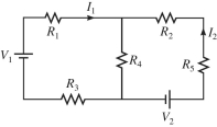
Correct Answer:

Verified
(a)V1 = 12 ...View Answer
Unlock this answer now
Get Access to more Verified Answers free of charge
Correct Answer:
Verified
View Answer
Unlock this answer now
Get Access to more Verified Answers free of charge
Q26: When an initially uncharged capacitor is charged
Q27: A series circuit consists of a 2.5-μF
Q99: For the circuit shown in the figure,
Q100: The resistors in the circuit shown
Q101: A network of capacitors is connected across
Q102: Three light bulbs, A, B, and C,
Q105: Two capacitors are connected as shown in
Q106: The network shown is assembled with
Q108: For the circuit shown in the figure,
Q146: What different resistances can be obtained by