Multiple Choice
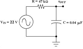
-If the output were taken across the resistor in Figure 10 -3, the circuit would be known as a .
A) low -pass filter
B) band -notch filter
C) band -pass filter
D) high -pass filter
Correct Answer:

Verified
Correct Answer:
Verified
Q34: <img src="https://d2lvgg3v3hfg70.cloudfront.net/TB3685/.jpg" alt=" -What is
Q35: <img src="https://d2lvgg3v3hfg70.cloudfront.net/TB3685/.jpg" alt=" -What is
Q37: <img src="https://d2lvgg3v3hfg70.cloudfront.net/TB3685/.jpg" alt=" -What is
Q37: Power factor values close to 0 denotes
Q38: <img src="https://d2lvgg3v3hfg70.cloudfront.net/TB3685/.jpg" alt=" -If the
Q40: <img src="https://d2lvgg3v3hfg70.cloudfront.net/TB3685/.jpg" alt=" -If the
Q41: <img src="https://d2lvgg3v3hfg70.cloudfront.net/TB3685/.jpg" alt=" -Calculate the
Q42: <img src="https://d2lvgg3v3hfg70.cloudfront.net/TB3685/.jpg" alt=" -Calculate the
Q44: <img src="https://d2lvgg3v3hfg70.cloudfront.net/TB3685/.jpg" alt=" -If the
Q63: As the frequency applied to an RC