Short Answer
For the circuit shown in the figure, , and , and the battery is ideal.
(a) What is the equivalent resistance across the battery?
(b) Find the current through each resistor.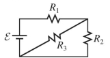
Correct Answer:

Verified
Correct Answer:
Verified
Related Questions
Q204: At what frequency will a
Q205: A <span class="ql-formula" data-value="6.0 -
Q206: At what frequency will the inductive
Q207: A certain ac signal at
Q208: A 120-V rms signal at
Q210: What is the rms current through
Q211: What is the equivalent resistance between
Q212: An ideal transformer steps down 120 V
Q213: A 120- <span class="ql-formula" data-value="\mathrm
Q214: A circuit contains a 2.0-M resistor