Short Answer
For the circuit shown in the figure, the ideal battery has an emf . The four resistors have resistances of , and . Calculate the rate at which heat is being generated in the resistor .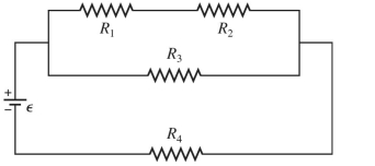
Correct Answer:

Verified
Correct Answer:
Verified
Related Questions
Q365: A <span class="ql-formula" data-value="0.150 -
Q366: A multiloop circuit is shown in
Q367: Each of the resistors shown in
Q368: What is the equivalent resistance of
Q369: An ideal transformer with 120 turns in
Q371: A battery has an emf
Q372: A conducting rod whose length is
Q373: A <span class="ql-formula" data-value="120 -
Q374: A 4.0- <span class="ql-formula" data-value="\Omega"><span
Q375: Four resistors are connected across an