Multiple Choice
In the circuit shown in the figure, , and the batteries are both ideal. What is the current through ?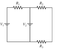
A)
B)
C)
D)
Correct Answer:

Verified
Correct Answer:
Verified
Related Questions
Q85: The network shown is assembled with
Q86: A battery has an emf
Q87: The resistors in the circuit shown
Q88: A number of resistors are connected
Q89: Two resistors in series are equivalent
Q91: A 25.0-mH inductor, a 2.00-
Q92: In the figure, a bar magnet
Q93: Two 100-W light bulbs of fixed resistance
Q94: An ideal solenoid with 3000 turns
Q95: A combination of a <span