Short Answer
For the circuit shown in the figure, , , and the batteries are ideal.
(a) Determine and .
(b) What is the potential difference across ?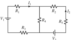
Correct Answer:

Verified
Correct Answer:
Verified
Related Questions
Q279: What capacitance will have the same
Q280: What is the potential drop from
Q281: It is known that birds can
Q282: A heating element having a resistance
Q283: A rectangular loop of wire that
Q285: The figure shows a series ac
Q286: A 5- <span class="ql-formula" data-value="\mu
Q287: A series circuit consists of a
Q288: A multiloop circuit is shown in
Q289: In the circuit shown in the