Short Answer
Examine the circuit shown in Figure 18-14.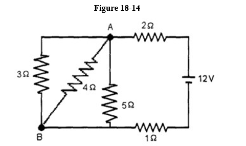
(a) Determine the current in each resistor.
(b) Determine the potential difference between points A and B.
Correct Answer:

Verified
(a) 2.8 A in 1. Ω and 2. Ω res...View Answer
Unlock this answer now
Get Access to more Verified Answers free of charge
Correct Answer:
Verified
(a) 2.8 A in 1. Ω and 2. Ω res...
View Answer
Unlock this answer now
Get Access to more Verified Answers free of charge
Related Questions
Q56: When two or more resistors are connected
Q57: A galvanometer with a coil resistance
Q58: Kirchhoff's junction rule is an example of<br>A)
Q59: State Kirchhoff's junction theorem.
Q60: A 4.0 M<img src="https://d2lvgg3v3hfg70.cloudfront.net/TB9720/.jpg" alt=" A
Q62: Which of the equations here is valid
Q63: Three identical resistors are connected in series
Q64: Shown in Figure 18-21 are a few
Q65: Consider a galvanometer with full scale
Q66: Find the equivalent resistance of the network