Multiple Choice
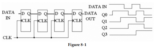
-The circuit in Figure 8- 1 fails to produce the proper data output. The individual flip- flops are checked with a logic probe and pulser and each checks OK. What is the most likely cause of the problem?
A) The data output line is grounded.
B) One of the flip- flops has a solder bridge between its input and Vcc.
C) One of the interconnect lines between two stages has a solder bridge to ground.
D) One of the clock input lines is open.
Correct Answer:

Verified
Correct Answer:
Verified
Q24: <img src="https://d2lvgg3v3hfg70.cloudfront.net/TB9838/.jpg" alt=" -Refer to Figure
Q25: <img src="https://d2lvgg3v3hfg70.cloudfront.net/TB9838/.jpg" alt=" -After the DATA
Q26: <img src="https://d2lvgg3v3hfg70.cloudfront.net/TB9838/.jpg" alt=" -Refer to Figure
Q27: An effective time delay device can be
Q28: <img src="https://d2lvgg3v3hfg70.cloudfront.net/TB9838/.jpg" alt=" -Refer to the
Q30: What is the modulus of a 6-
Q31: <img src="https://d2lvgg3v3hfg70.cloudfront.net/TB9838/.jpg" alt=" -Refer to Figure
Q32: What does UART stand for, and what
Q33: <img src="https://d2lvgg3v3hfg70.cloudfront.net/TB9838/.jpg" alt=" -What type of
Q34: A serial data path needs a 2000