Multiple Choice
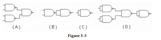
-Which circuit in Figure 5- 3 represents the NAND implementation of an inverter?
A) Figure (A) .
B) Figure (B) .
C) Figure (C) .
D) Figure (D) .
Correct Answer:

Verified
Correct Answer:
Verified
Related Questions
Q1: The NAND gate is an example of
Q2: Which figure below represents AND- OR logic?<br><img
Q4: The Karnaugh map below represents the expression,
Q5: The NAND gate is referred to as
Q6: How many gates, including inverters, are required
Q7: <img src="https://d2lvgg3v3hfg70.cloudfront.net/TB9838/.jpg" alt=" -Based on the
Q8: <img src="https://d2lvgg3v3hfg70.cloudfront.net/TB9838/.jpg" alt=" -Which circuit in
Q9: NOR gates can be used to construct
Q10: <img src="https://d2lvgg3v3hfg70.cloudfront.net/TB9838/.jpg" alt=" -Which circuit in
Q11: Which of the figures is the correct