Multiple Choice
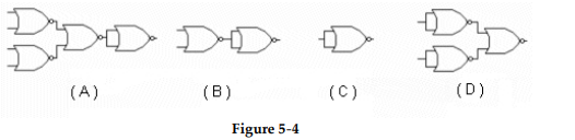
-Which circuit in Figure 5- 4 represents the NOR implementation of an inverter?
A) Figure (A)
B) Figure (B)
C) Figure (C)
D) Figure (D)
Correct Answer:

Verified
Correct Answer:
Verified
Related Questions
Q12: <img src="https://d2lvgg3v3hfg70.cloudfront.net/TB9838/.jpg" alt=" -What type of
Q13: This circuit is an example of the
Q14: The output of a gate has an
Q15: <img src="https://d2lvgg3v3hfg70.cloudfront.net/TB9838/.jpg" alt=" -Based on the
Q16: How many gates, including inverters, are required
Q18: NAND gates cannot be used to construct
Q19: What is the indication of a short
Q20: When the inverted output of one gate
Q21: <img src="https://d2lvgg3v3hfg70.cloudfront.net/TB9838/.jpg" alt=" " class="answers-bank-image d-inline" rel="preload"
Q22: Why are multiple NAND gates often used