Multiple Choice
The timing diagram below is correct for a 2- input _________ gate.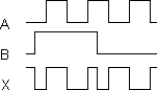
A) Exclusive- OR
B) AND
C) Exclusive- NOR
D) NAND
Correct Answer:

Verified
Correct Answer:
Verified
Q18: When the inputs to a 3- input
Q19: A logic gate draws 10mA when its
Q20: The symbol below represents a(n)_ .<br><img src="https://d2lvgg3v3hfg70.cloudfront.net/TB9838/.jpg"
Q21: A circle, or "bubble," on a distinctive-
Q22: The term "hex inverter" refers to _.<br>A)
Q24: The symbol below represents a(n) _.<br>?<br><img src="https://d2lvgg3v3hfg70.cloudfront.net/TB9838/.jpg"
Q25: The OR gate performs a function similar
Q26: The truth table below describes a(n) _<br>?
Q27: The symbol below represents a(n) _ .<br><img src="https://d2lvgg3v3hfg70.cloudfront.net/TB9838/.jpg"
Q28: The symbol below represents a(n) _.<br><img src="https://d2lvgg3v3hfg70.cloudfront.net/TB9838/.jpg"