menu-iconExamlexExamLexServices

Discover

Ask a Question
  1. All Topics
  2. Topic
    Physics & Astronomy
  3. Study Set
    Physics Study Set 1
  4. Exam
    Exam 21: Electric Current and Direct-Current Circuits
  5. Question
    In the Circuit Shown in the Figure,R<sub>1</sub> = 10 Ω,R<sub>2</sub>
Solved

In the Circuit Shown in the Figure,R1 = 10 Ω,R2

Question 39

Question 39

Multiple Choice

In the circuit shown in the figure,R1 = 10 Ω,R2 = 12 Ω,R3 = 20 Ω,V1 = 1.0 V,V2 = 7.0 V,and the batteries are both ideal.What is the current through R1?
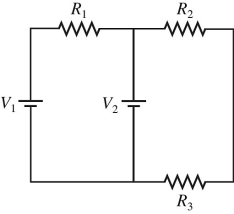
 In the circuit shown in the figure,R<sub>1</sub> = 10 Ω,R<sub>2</sub> = 12 Ω,R<sub>3</sub> = 20 Ω,V<sub>1</sub> = 1.0 V,V<sub>2</sub> = 7.0 V,and the batteries are both ideal.What is the current through R<sub>1</sub>?   A) 0.60 A B) 0.80 A C) 0.18 A D) 0.13 A


A) 0.60 A
B) 0.80 A
C) 0.18 A
D) 0.13 A

Correct Answer:

verifed

Verified

Unlock this answer now
Get Access to more Verified Answers free of charge

Related Questions

Q34: A 1.0-μF capacitor is charged until it

Q35: For the circuit shown in the figure,C

Q36: What is the potential drop from point

Q37: What is the resistance of 1.0 m

Q38: A capacitor C is connected in series

Q40: A simple circuit has a total resistance

Q41: When different resistors are connected in parallel

Q42: A 400-W computer (including its monitor)is turned

Q43: Three identical capacitors are connected in series

Q44: What is the voltage drop across a

Examlex

ExamLex

About UsContact UsPerks CenterHomeschoolingTest Prep

Work With Us

Campus RepresentativeInfluencers

Links

FaqPricingChrome Extension

Download The App

Get App StoreGet Google Play

Policies

Privacy PolicyTerms of ServiceHonor CodeCommunity Guidelines

Scan To Download

qr-code

Copyright © (2025) ExamLex LLC.

Privacy PolicyTerms Of ServiceHonor CodeCommunity Guidelines