True/False
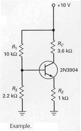
In the circuit shown in Figure 7-12,the first step in finding the emitter current is to determine the voltage across R2.
Correct Answer:

Verified
Correct Answer:
Verified
Related Questions
Q21: Emitter-feedback and collector-feedback bias circuits are inadequate
Q22: The emitter-base junction voltage of the silicon
Q23: In Figure 7-5,when the fuse is not
Q24: Emitter bias is used to stabilize the
Q25: Emitter-feedback bias has never become popular because
Q27: In Figure 7-18,the positive supply <img src="https://d2lvgg3v3hfg70.cloudfront.net/TB4790/.jpg"
Q28: Some electronic equipment has a power supply
Q29: Emitter-feedback and collector-feedback are typically not adequate
Q30: Collector-feedback bias is more effective than emitter-feedback
Q31: If R<sub>E</sub> is adjusted it its minimum