menu-iconExamlexExamLexServices

Discover

Ask a Question
  1. All Topics
  2. Topic
    Engineering
  3. Study Set
    Electronic Principles
  4. Exam
    Exam 4: Diode Circuits
  5. Question
    The Output as Measured Across R<sub>L</sub> in Figure 4-6 (A)would
Solved

The Output as Measured Across RL in Figure 4-6 (A)would

Question 37

Question 37

Multiple Choice

The output as measured across RL in Figure 4-6 (a) would be
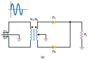
 The output as measured across R<sub>L</sub> in Figure 4-6 (a) would be   A)  pulsating dc. B)  alternating current. C)  negative dc pulses. D)  a square wave.


A) pulsating dc.
B) alternating current.
C) negative dc pulses.
D) a square wave.

Correct Answer:

verifed

Verified

Unlock this answer now
Get Access to more Verified Answers free of charge

Related Questions

Q32: An advantage of the full-wave voltage doubler

Q33: What is the output signal across R<sub>L</sub>?

Q34: The dc value of a signal is

Q35: Another name for diode offset voltage is<br>A)

Q36: What type of power supply circuit is

Q38: What is term for a special kind

Q39: Applying an external voltage to change the

Q40: The output frequency of a half-wave rectifier

Q41: What type of filters are configured using

Q42: The full-wave rectifier is equivalent to three

Examlex

ExamLex

About UsContact UsPerks CenterHomeschoolingTest Prep

Work With Us

Campus RepresentativeInfluencers

Links

FaqPricingChrome Extension

Download The App

Get App StoreGet Google Play

Policies

Privacy PolicyTerms of ServiceHonor CodeCommunity Guidelines

Scan To Download

qr-code

Copyright © (2025) ExamLex LLC.

Privacy PolicyTerms Of ServiceHonor CodeCommunity Guidelines