Short Answer
For the circuit shown in the figure, R1 = 5.6 Ω, R2 = 5.6 Ω, R3 = 14 Ω, and ε = 6.0 V, and the battery is ideal.
(a) What is the equivalent resistance across the battery?
(b) Find the current through each resistor. 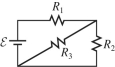
Correct Answer:

Verified
(a) 9.6 Ω ...View Answer
Unlock this answer now
Get Access to more Verified Answers free of charge
Correct Answer:
Verified
View Answer
Unlock this answer now
Get Access to more Verified Answers free of charge
Q9: Two resistors in series are equivalent to
Q10: For the circuit shown in the figure,
Q11: For the circuit shown in the figure,
Q13: Three resistors with resistances of 2.0 Ω,
Q16: A number of resistors are connected across
Q17: If emf of the ideal battery is
Q18: What is the equivalent resistance between points
Q19: Three capacitors of equal capacitance are
Q51: An ideal 100-V dc battery is applied
Q153: A fully charged 37-µF capacitor is discharged