menu-iconExamlexExamLexServices

Discover

Ask a Question
  1. All Topics
  2. Topic
    Physics & Astronomy
  3. Study Set
    College Physics
  4. Exam
    Exam 23: Circuits
  5. Question
    For the Circuit Shown in the Figure, Calculate the Emf's
Solved

For the Circuit Shown in the Figure, Calculate the Emf's

Question 60

Question 60

Short Answer

For the circuit shown in the figure, calculate the emf's ε1 and ε3, assuming that the batteries are ideal. Note that two currents are shown.
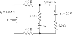
 For the circuit shown in the figure, calculate the emf's ε<sub>1</sub> and ε<sub>3</sub>, assuming that the batteries are ideal. Note that two currents are shown.

Correct Answer:

verifed

Verified

Unlock this answer now
Get Access to more Verified Answers free of charge

Related Questions

Q12: When unequal resistors are connected in parallel

Q13: Two 4.0-Ω resistors are connected in parallel,and

Q20: Four resistors having resistances of 20 Ω,40

Q55: A multiloop circuit is shown in the

Q56: What is the magnitude of the potential

Q57: Two resistors with resistances of 5.0 Ω

Q62: Determine the current in the 7.0-Ω resistor

Q65: A 5-µF, a 7-µF, and an unknown

Q93: A 22-A current flows into a parallel

Q168: A15-Ω resistor is connected in parallel with

Examlex

ExamLex

About UsContact UsPerks CenterHomeschoolingTest Prep

Work With Us

Campus RepresentativeInfluencers

Links

FaqPricingChrome Extension

Download The App

Get App StoreGet Google Play

Policies

Privacy PolicyTerms of ServiceHonor CodeCommunity Guidelines

Scan To Download

qr-code

Copyright © (2025) ExamLex LLC.

Privacy PolicyTerms Of ServiceHonor CodeCommunity Guidelines