Short Answer
For the circuit shown in the figure, R1 = 50 Ω, R2 = 20 Ω, R3 = 35 Ω, R4 = 10 Ω, R5 = 68 Ω, I1 = 0.111 A, I2 = 0.142 A, and the batteries are ideal.
(a) Determine V1 and V2.
(b) What is the potential difference across R4? 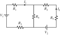
Correct Answer:

Verified
(a) V1 = 12...View Answer
Unlock this answer now
Get Access to more Verified Answers free of charge
Correct Answer:
Verified
View Answer
Unlock this answer now
Get Access to more Verified Answers free of charge
Q6: Four unequal resistors are connected in series
Q96: Three resistors of resistances 4.0 Ω,6.0 Ω,and
Q120: For the circuit shown in the figure,
Q121: A charged capacitor is connected in series
Q123: The network shown is assembled with uncharged
Q125: Five 2.0-Ω resistors are connected as shown
Q126: Determine the current in the 12-Ω resistor
Q139: Kirchhoff's loop rule is a statement of<br>A)the
Q160: A 2.0-μF capacitor is charged to 12
Q221: Kirchhoff's junction rule is a statement of<br>A)the