Multiple Choice
Refer to the figure showing different lever systems. 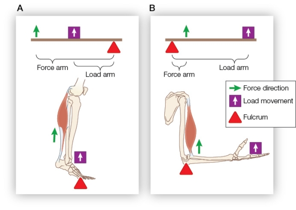 The position of the fulcrum and the ratios of the lengths of the load arm and force arm indicate that lever(s) _______ is/are _______.
A) A; maximized for speed because the ratio of the load arm to force arm is 1:2
B) B; maximized for speed because the ratio of the load arm to force arm is 5:1
C) A and B; both maximized for force because the fulcrum is not positioned between the load arm and force arm
D) A; a class 1 lever because the fulcrum is located between the load and the point of force application
E) B; a class 2 lever because the load is located between the fulcrum and the point of force application
Correct Answer:

Verified
Correct Answer:
Verified
Q118: Which feature is an advantage of endoskeletons
Q119: Which statement about growing long bones of
Q120: If a spontaneous mutation arose in the
Q121: Which muscle type(s) use(s) calcium to trigger
Q122: Which event occurs during skeletal and cardiac
Q124: Which pairing of a sarcomere structure with
Q125: Refer to the figure showing muscle cells.
Q126: When you lift a cup of coffee
Q127: Bone tissue includes _ cells enclosed in
Q128: Which statement about the long bones in