Short Answer
For the circuit shown in the figure, determine the current in
(a) the 7.0-Ω resistor.
(b) the 8.0-Ω resistor.
(c) the 4.0-Ω resistor. 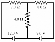
Correct Answer:

Verified
(a) 1.6 A ...View Answer
Unlock this answer now
Get Access to more Verified Answers free of charge
Correct Answer:
Verified
(a) 1.6 A ...
View Answer
Unlock this answer now
Get Access to more Verified Answers free of charge
Related Questions
Q5: A 5.0-Ω resistor and a 9.0-Ω resistor
Q11: A galvanometer has an internal resistance of
Q16: A 4.00-Ω resistor,an 8.00-Ω resistor,and a 24.0-Ω
Q26: For the circuit shown in the figure,
Q27: For the circuit shown in the figure,
Q28: Consider the circuit shown in the figure.
Q30: When four identical resistors are connected to
Q30: Three resistors having resistances of 4.0 Ω,6.0
Q34: In the circuit shown in the figure,
Q35: An uncharged 1.0-μF capacitor is connected in