Multiple Choice
Use the following figure for the next problem. 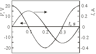
-The figure shows the voltage and current for a(n)
A) inductor.
B) capacitor.
C) resistor.
D) inductor and capacitor.
E) inductor and resistor.
Correct Answer:

Verified
Correct Answer:
Verified
Related Questions
Q86: For a capACitor,the<br>A)voltage lags behind the current.<br>B)current
Q87: A 5-µF capacitor is charged to
Q88: A series RLC circuit with L
Q89: A series RLC circuit with L
Q90: A 15- <span class="ql-formula" data-value="\Omega"><span class="katex"><span
Q92: You connect a 100- <span class="ql-formula"
Q93: How much does the maximum EMF produced
Q94: A 200-turn coil rotates in a magnetic
Q95: At what frequency would the reactance
Q96: If you double the peak voltage in