Short Answer
Refer to the figure below to answer the following questions.
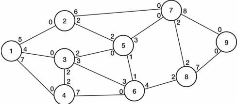 Figure 3
-Consider the network diagram given in Figure 3 with the indicated flow capacities along each branch. Determine the maximal flow on the following path: node 1 to node 2 to node 7 to destination node 9.
Correct Answer:

Verified
Correct Answer:
Verified
Q73: Consider the following network, which shows the
Q74: The values assigned to branches typically represent
Q75: If we wanted to represent an office
Q76: <img src="https://d2lvgg3v3hfg70.cloudfront.net/TB2836/.jpg" alt=" -How much longer
Q77: <img src="https://d2lvgg3v3hfg70.cloudfront.net/TB2836/.jpg" alt=" -If the two
Q79: <img src="https://d2lvgg3v3hfg70.cloudfront.net/TB2836/.jpg" alt=" Figure 2 -Consider
Q80: Refer to the figure below to answer
Q81: Once a decision maker has determined the
Q82: To determine the maximum possible flow of
Q83: Pro-Carpet company manufactures carpets in Northwest Indiana