Deck 8: Axially Loaded Members
Full screen (f)
Question


Question
plane truss with span length L 5 4.5 m is constructed using cast iron pipes  with a cross-sectional area of
  The displacement of joint B cannot exceed 2.7 mm. The maximum value of
Loads P is approximately: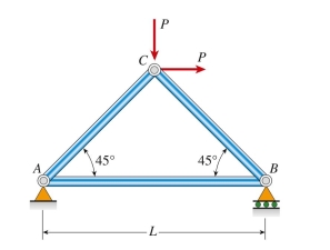
(A) 340 kN
(B) 460 kN
(C) 510 kN
(D) 600 kN
with a cross-sectional area of The displacement of joint B cannot exceed 2.7 mm. The maximum value ofLoads P is approximately:
(A) 340 kN
(B) 460 kN
(C) 510 kN
(D) 600 kN
Question
wires, one copper and the other steel, of equal length stretch the same amount under an applied load P. The moduli of elasticity for each is  GPa. The ratio of the diameter of the copper
Wire to that of the steel wire is approximately: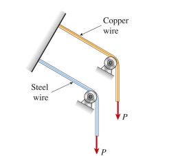
(A) 1.00
(B) 1.08
(C) 1.19
(D) 1.32
GPa. The ratio of the diameter of the copperWire to that of the steel wire is approximately:
(A) 1.00
(B) 1.08
(C) 1.19
(D) 1.32
Question
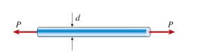
A copper bar (d 5 10 mm, E 5 110 GPa) is loaded by tensile load P 5 11.5 kN. The maximum shear stress in the bar is approximately: 
Question
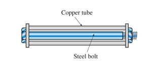
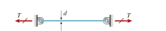
A steel bolt (area  is enclosed by a copper tube (length 5 0.5 m, area 5
 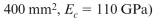 110 GPa) and the end nut is turned until it is just snug. The pitch of the bolt threads is 1.25 mm. The bolt is now tightened by a quarter turn of the nut. The resulting stress in the bolt is approximately:
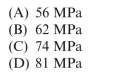
is enclosed by a copper tube (length 5 0.5 m, area 5 110 GPa) and the end nut is turned until it is just snug. The pitch of the bolt threads is 1.25 mm. The bolt is now tightened by a quarter turn of the nut. The resulting stress in the bolt is approximately: Question
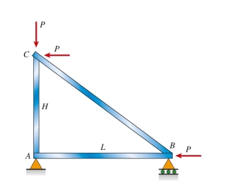
A steel plane truss is loaded at B and C by forces P 5 200 kN. The cross-sectional area of each member 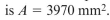 . Truss dimensions are H 5 3 m and L 5 4 m. The maximum shear stress in bar AB is approx- imately:
. Truss dimensions are H 5 3 m and L 5 4 m. The maximum shear stress in bar AB is approx- imately: Question
nylon bar (E 5 2.1 GPa) with diameter 12 mm, length 4.5 m, and weight 5.6 N hangs vertically under its own weight. The elongation of the bar at its free end is approximately: 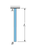
(A) 0.05 mm
(B) 0.07 mm
(C) 0.11 mm
(D) 0.17 mm
(A) 0.05 mm
(B) 0.07 mm
(C) 0.11 mm
(D) 0.17 mm
Question
brass bar (E 5 110 MPa) of length  18 mm over one-half of its length and
 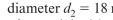 18 mm over the other half. Compare this nonprismatic bar to a prismatic bar of the same volume of material with constant diameter d and length L. The elongation of the prismatic bar under the same load
P 5 25 kN is approximately:
(A) 3 mm
(B) 4 mm
(C) 5 mm
(D) 6 mm
18 mm over one-half of its length and 18 mm over the other half. Compare this nonprismatic bar to a prismatic bar of the same volume of material with constant diameter d and length L. The elongation of the prismatic bar under the same loadP 5 25 kN is approximately:
(A) 3 mm
(B) 4 mm
(C) 5 mm
(D) 6 mm
Question
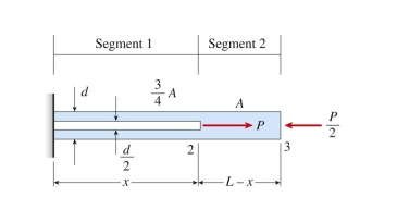
nonprismatic cantilever bar has an internal cylindrical hole of diameter  /2 from 0 to x, so the net area of the cross section for Segment 1 is (3/4)
 /2 is applied at x 5 L. Assume
That E is constant. The length of the hollow segment, x, required to obtain axial displacement δ 5 PL/EA at the
Free end is:
/2 from 0 to x, so the net area of the cross section for Segment 1 is (3/4) /2 is applied at x 5 L. AssumeThat E is constant. The length of the hollow segment, x, required to obtain axial displacement δ 5 PL/EA at the
Free end is:
Question
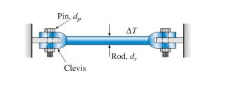
A brass wire (d 5 2.0 mm, E 5 110 GPa) is pretensioned to T 5 85 N. The coefficient of thermal expan- sion for the wire is 19.5  /°C. The temperature change at which the wire goes slack is approximately:
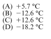
/°C. The temperature change at which the wire goes slack is approximately: Question


(A) 0.9 mm
(B) 1.6 mm
(C) 2.1 mm
(D) 3.4 mm
Question


Question
A plane stress element on a bar in uniaxial stress has a tensile stress of  78 MPa (see figure). The maximum shear stress in the bar is approximately:
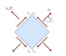
78 MPa (see figure). The maximum shear stress in the bar is approximately: Question
A prismatic bar (diameter 

 Torsional stresses and deformations; power transmission
(A) 0.9
(B) 1.2
(C) 1.4
(D) 2.1
Torsional stresses and deformations; power transmission(A) 0.9
(B) 1.2
(C) 1.4
(D) 2.1
Question
A steel bar of rectangular cross section (a 5 38 mm, b 5 50 mm) carries a tensile load P. The allowable stresses in tension and shear are 100 MPa and 48 MPa, respectively. The maximum permissible load  is
is
Approximately:
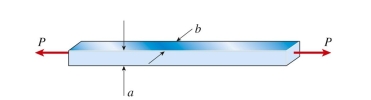
isApproximately:
Question
 Initially, both shell and core have a length of 100 mm. A load P is applied to both shell and core through a cap plate. The load P required to compress both shell and core by 0.10 mm is approximately:
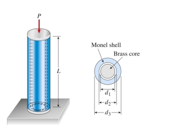
(A) 10.2 kN
(B) 13.4 kN
(C) 18.5 kN
(D) 21.0 kN

Unlock Deck
Sign up to unlock the cards in this deck!
Unlock Deck
Unlock Deck
1/16
Play
Full screen (f)
Deck 8: Axially Loaded Members
1
C
2
plane truss with span length L 5 4.5 m is constructed using cast iron pipes with a cross-sectional area of The displacement of joint B cannot exceed 2.7 mm. The maximum value of
Loads P is approximately:
(A) 340 kN
(B) 460 kN
(C) 510 kN
(D) 600 kN
with a cross-sectional area of The displacement of joint B cannot exceed 2.7 mm. The maximum value ofLoads P is approximately:
(A) 340 kN
(B) 460 kN
(C) 510 kN
(D) 600 kN
B
3
wires, one copper and the other steel, of equal length stretch the same amount under an applied load P. The moduli of elasticity for each is GPa. The ratio of the diameter of the copper
Wire to that of the steel wire is approximately:
(A) 1.00
(B) 1.08
(C) 1.19
(D) 1.32
GPa. The ratio of the diameter of the copperWire to that of the steel wire is approximately:
(A) 1.00
(B) 1.08
(C) 1.19
(D) 1.32
D
4
A copper bar (d 5 10 mm, E 5 110 GPa) is loaded by tensile load P 5 11.5 kN. The maximum shear stress in the bar is approximately:
Unlock Deck
Unlock for access to all 16 flashcards in this deck.
Unlock Deck
k this deck
5
A steel bolt (area is enclosed by a copper tube (length 5 0.5 m, area 5 110 GPa) and the end nut is turned until it is just snug. The pitch of the bolt threads is 1.25 mm. The bolt is now tightened by a quarter turn of the nut. The resulting stress in the bolt is approximately:
is enclosed by a copper tube (length 5 0.5 m, area 5 110 GPa) and the end nut is turned until it is just snug. The pitch of the bolt threads is 1.25 mm. The bolt is now tightened by a quarter turn of the nut. The resulting stress in the bolt is approximately: Unlock Deck
Unlock for access to all 16 flashcards in this deck.
Unlock Deck
k this deck
6
A steel plane truss is loaded at B and C by forces P 5 200 kN. The cross-sectional area of each member . Truss dimensions are H 5 3 m and L 5 4 m. The maximum shear stress in bar AB is approx- imately:
. Truss dimensions are H 5 3 m and L 5 4 m. The maximum shear stress in bar AB is approx- imately: Unlock Deck
Unlock for access to all 16 flashcards in this deck.
Unlock Deck
k this deck
7
nylon bar (E 5 2.1 GPa) with diameter 12 mm, length 4.5 m, and weight 5.6 N hangs vertically under its own weight. The elongation of the bar at its free end is approximately:
(A) 0.05 mm
(B) 0.07 mm
(C) 0.11 mm
(D) 0.17 mm
(A) 0.05 mm
(B) 0.07 mm
(C) 0.11 mm
(D) 0.17 mm
Unlock Deck
Unlock for access to all 16 flashcards in this deck.
Unlock Deck
k this deck
8
brass bar (E 5 110 MPa) of length 18 mm over one-half of its length and 18 mm over the other half. Compare this nonprismatic bar to a prismatic bar of the same volume of material with constant diameter d and length L. The elongation of the prismatic bar under the same load
P 5 25 kN is approximately:
(A) 3 mm
(B) 4 mm
(C) 5 mm
(D) 6 mm
18 mm over one-half of its length and 18 mm over the other half. Compare this nonprismatic bar to a prismatic bar of the same volume of material with constant diameter d and length L. The elongation of the prismatic bar under the same loadP 5 25 kN is approximately:
(A) 3 mm
(B) 4 mm
(C) 5 mm
(D) 6 mm
Unlock Deck
Unlock for access to all 16 flashcards in this deck.
Unlock Deck
k this deck
9
nonprismatic cantilever bar has an internal cylindrical hole of diameter /2 from 0 to x, so the net area of the cross section for Segment 1 is (3/4) /2 is applied at x 5 L. Assume
That E is constant. The length of the hollow segment, x, required to obtain axial displacement δ 5 PL/EA at the
Free end is:
/2 from 0 to x, so the net area of the cross section for Segment 1 is (3/4) /2 is applied at x 5 L. AssumeThat E is constant. The length of the hollow segment, x, required to obtain axial displacement δ 5 PL/EA at the
Free end is:
Unlock Deck
Unlock for access to all 16 flashcards in this deck.
Unlock Deck
k this deck
10
A brass wire (d 5 2.0 mm, E 5 110 GPa) is pretensioned to T 5 85 N. The coefficient of thermal expan- sion for the wire is 19.5 /°C. The temperature change at which the wire goes slack is approximately:
/°C. The temperature change at which the wire goes slack is approximately: Unlock Deck
Unlock for access to all 16 flashcards in this deck.
Unlock Deck
k this deck
11
(A) 0.9 mm
(B) 1.6 mm
(C) 2.1 mm
(D) 3.4 mm
Unlock Deck
Unlock for access to all 16 flashcards in this deck.
Unlock Deck
k this deck
12
Unlock Deck
Unlock for access to all 16 flashcards in this deck.
Unlock Deck
k this deck
13
A plane stress element on a bar in uniaxial stress has a tensile stress of 78 MPa (see figure). The maximum shear stress in the bar is approximately:
78 MPa (see figure). The maximum shear stress in the bar is approximately: Unlock Deck
Unlock for access to all 16 flashcards in this deck.
Unlock Deck
k this deck
14
A prismatic bar (diameter Torsional stresses and deformations; power transmission
(A) 0.9
(B) 1.2
(C) 1.4
(D) 2.1
Torsional stresses and deformations; power transmission(A) 0.9
(B) 1.2
(C) 1.4
(D) 2.1
Unlock Deck
Unlock for access to all 16 flashcards in this deck.
Unlock Deck
k this deck
15
A steel bar of rectangular cross section (a 5 38 mm, b 5 50 mm) carries a tensile load P. The allowable stresses in tension and shear are 100 MPa and 48 MPa, respectively. The maximum permissible load is
Approximately:
isApproximately:
Unlock Deck
Unlock for access to all 16 flashcards in this deck.
Unlock Deck
k this deck
16
Initially, both shell and core have a length of 100 mm. A load P is applied to both shell and core through a cap plate. The load P required to compress both shell and core by 0.10 mm is approximately: (A) 10.2 kN
(B) 13.4 kN
(C) 18.5 kN
(D) 21.0 kN
Unlock Deck
Unlock for access to all 16 flashcards in this deck.
Unlock Deck
k this deck
Unlock Deck
Unlock for access to all 16 flashcards in this deck.


