Exam 12: Rlcircuits
Exam 1: Systems, Quantities, and Units41 Questions
Exam 2: Voltage, Current, and Resistance71 Questions
Exam 3: Ohms Law, Energy, and Power69 Questions
Exam 4: Series Circuits67 Questions
Exam 5: Parallel Circuits66 Questions
Exam 6: Series-Parallel Circuits73 Questions
Exam 7: Magnetism and Electromagnetism69 Questions
Exam 8: Introduction to Alternating Current and Voltage74 Questions
Exam 9: Capacitors69 Questions
Exam 10: Rccircuits66 Questions
Exam 11: Inductors66 Questions
Exam 12: Rlcircuits67 Questions
Exam 13: Rlccircuits and Resonance70 Questions
Exam 14: Transformers69 Questions
Exam 15: Time Response of Reactive Circuits68 Questions
Select questions type
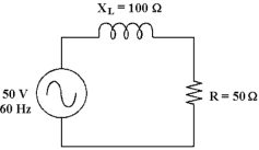 -If the frequency is 400 Hz in Figure 12 -1, what is the inductance?
Free
(Multiple Choice)
4.7/5  (35)
(35)
Correct Answer: Verified
A
-If the frequency increases in Figure 12 -1, the phase angle and the current _.
Free
(Multiple Choice)
4.9/5 (38)
Correct Answer:Verified
D
An ohmmeter can be used to accurately test the impedance of an RL circuit.
Free
(True/False)
4.8/5 (37)
Correct Answer:Verified
False
The output at the cutoff frequency of a low pass RL filter is 0 V.
(True/False)
4.7/5 (36)
-If the frequency decreases in Figure 12 -1, the phase angle and the impedance _.
(Multiple Choice)
4.9/5 (41)
A low -pass filter passes high frequencies and blocks other frequencies.
(True/False)
4.8/5 (29)
 -If the resistor decreases in Figure 12 -2, the total current _ _.
(Multiple Choice)
4.7/5 (46)
The startup current for large induction motors is very high because
(Multiple Choice)
4.9/5 (35)
-If the operating frequency decreases in Figure 12 -1, the inductance .
(Multiple Choice)
4.8/5 (31)
The voltage measured across the inductor in a series RL has dropped significantly from normal. What could possibly be the problem?
(Multiple Choice)
4.9/5 (29)
-If the frequency decreases in Figure 12 -1, the phase angle and the current _.
(Multiple Choice)
4.8/5 (33)
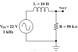 -What is the phase angle in Figure 12 -3, at the cutoff frequency?
(Multiple Choice)
4.9/5 (37)
The impedance of an RL series circuit varies inversely with the frequency.
(True/False)
4.9/5 (34)
Power dissipated by the resistor in a parallel RL circuit can be increased with the addition of a capacitor in parallel.
(True/False)
4.8/5 (32)
A measured voltage of 0 V across the resistor in a parallel RL circuit would indicate:
(Multiple Choice)
4.9/5 (39)
-If the frequency is 60 Hz in Figure 12 -1, what is the inductance?
(Multiple Choice)
4.9/5 (40)
Filters
- Essay(0)
- Multiple Choice(0)
- Short Answer(0)
- True False(0)
- Matching(0)