Exam 16: Engineering Drawings and Symbols
Exam 1: Introduction to the Engineering Profession24 Questions
Exam 2: Preparing for an Engineering Career24 Questions
Exam 3: Introduction to Engineering Design45 Questions
Exam 4: Engineering Communication33 Questions
Exam 5: Engineering Ethics21 Questions
Exam 6: Fundamental Dimensions and Units45 Questions
Exam 7: Length and Length-Related Variables in Engineering41 Questions
Exam 8: Time and Time-Related Variables in Engineering36 Questions
Exam 9: Mass and Mass-Related Variables in Engineering50 Questions
Exam 10: Force and Force-Related Variables in Engineering61 Questions
Exam 11: Temperature and Temperature-Related Variables in Engineering55 Questions
Exam 12: Electric Current and Related Variables in Engineering40 Questions
Exam 13: Energy and Power41 Questions
Exam 14: Computational Engineering Tools: Electronic Spreadsheets39 Questions
Exam 15: Computational Engineering Tools: Matlab38 Questions
Exam 16: Engineering Drawings and Symbols42 Questions
Exam 17: Engineering Materials66 Questions
Exam 18: Mathematics in Engineering50 Questions
Exam 19: Probability and Statistics in Engineering36 Questions
Exam 20: Engineering Economics45 Questions
Select questions type
Mechanical engineers use engineering symbols in their diagrams to show the
Free
(Multiple Choice)
4.9/5  (32)
(32)
Correct Answer: Verified
E
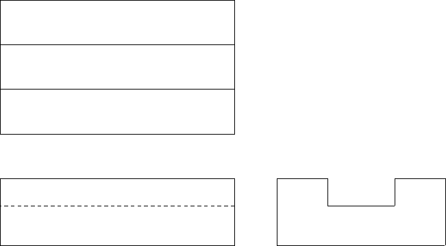
Shown below is an isometric drawing.Draw the top, front and right side views.
SHAPE \* MERGEFORMAT


Free
(Essay)
4.8/5 (34)
Correct Answer:Verified
SHAPE MERGEFORMAT

The view that shows the three dimensions of an object in a single view is known as
Free
(Multiple Choice)
4.8/5 (37)
Correct Answer:Verified
A
Shown below is an isometric drawing.Draw the top, front and right side views. 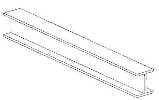
(Essay)
4.9/5 (36)
Shown below is an isometric drawing.Draw the top, front and right side views. 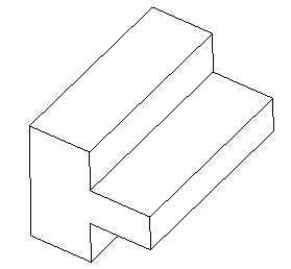
(Essay)
4.8/5 (31)
The American National Standards Institute (ANSI) does not set the standards for the dimensioning and tolerancing practices for engineering drawings.
(True/False)
4.8/5 (32)
In a sectional view, the solid portion of the view is marked with
(Multiple Choice)
4.8/5 (35)
The arrows that point to a circle or a fillet for the purpose of specifying their sizes are known as
(Multiple Choice)
4.9/5 (41)
CNC machines are often used to make parts directly from solid modeling software.What does CNC stand for?
(Multiple Choice)
4.8/5 (45)
It is not necessary for all engineering drawings to contain an information box with the following items: name of the person who prepared the drawing, title of the drawing, date, scale, sheet number, and drawing number.
(True/False)
4.8/5 (36)
On an engineering drawing, what does NTS typically stand for?
(Multiple Choice)
4.9/5 (35)
Electrical engineers use various symbols to represent the components that make up
(Multiple Choice)
4.9/5 (37)
Which three views are most commonly used to describe most objects?
(Multiple Choice)
4.8/5 (38)
A sectional view is created by making an imaginary cut through the object, in a certain direction, to reveal its interior.
(True/False)
4.7/5 (39)
Engineers use conventional engineering symbols as a means to convey information and to effectively communicate to other engineers.
(True/False)
4.9/5 (34)
Shown below is an isometric drawing.Draw the top, front and right side views. 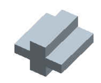
(Essay)
4.8/5 (34)
The views that show what an object's projection looks like when seen from the top, the front, and the side are known as
(Multiple Choice)
5.0/5 (49)
Shown below is an isometric drawing.Draw the top, front and right side views. 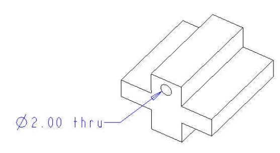
(Essay)
4.8/5 (39)
There are two ways to create a solid model of an object.What are they?
(Essay)
4.8/5 (42)
Filters
- Essay(0)
- Multiple Choice(0)
- Short Answer(0)
- True False(0)
- Matching(0)