Exam 16: Engineering Drawings and Symbols
Exam 1: Introduction to the Engineering Profession24 Questions
Exam 2: Preparing for an Engineering Career24 Questions
Exam 3: Introduction to Engineering Design45 Questions
Exam 4: Engineering Communication33 Questions
Exam 5: Engineering Ethics21 Questions
Exam 6: Fundamental Dimensions and Units45 Questions
Exam 7: Length and Length-Related Variables in Engineering41 Questions
Exam 8: Time and Time-Related Variables in Engineering36 Questions
Exam 9: Mass and Mass-Related Variables in Engineering50 Questions
Exam 10: Force and Force-Related Variables in Engineering61 Questions
Exam 11: Temperature and Temperature-Related Variables in Engineering55 Questions
Exam 12: Electric Current and Related Variables in Engineering40 Questions
Exam 13: Energy and Power41 Questions
Exam 14: Computational Engineering Tools: Electronic Spreadsheets39 Questions
Exam 15: Computational Engineering Tools: Matlab38 Questions
Exam 16: Engineering Drawings and Symbols42 Questions
Exam 17: Engineering Materials66 Questions
Exam 18: Mathematics in Engineering50 Questions
Exam 19: Probability and Statistics in Engineering36 Questions
Exam 20: Engineering Economics45 Questions
Select questions type
The lines that extend from the points to which the dimension or location is to be specified are known as
(Multiple Choice)
4.8/5  (43)
(43)
The computer-generated solid models save time and money and allow the engineer to perform additional engineering analysis, such as stress calculations or temperature distribution calculations for products.
(True/False)
4.9/5 (35)
Rotated section views may be used when the object has a uniform cross section with a shape that is difficult to visualize.In such cases, the cross section is rotated by 90° and is shown in the plane of view.
(True/False)
4.8/5 (41)
For objects with complex interiors, sectional views are used.Sectional views reveal the inside of the object.
(True/False)
4.8/5 (40)
The type of drawings that is common to civil engineering include land or boundary, topographic, construction, connection and reinforcement details, and route survey drawings.
(True/False)
4.7/5 (39)
Shown below is an isometric drawing.Draw the top, front and right side views. 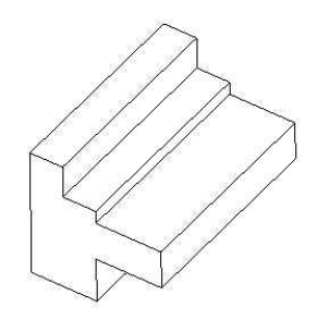
(Essay)
4.7/5 (33)
Shown below is an isometric drawing.Draw the top, front and right side views. 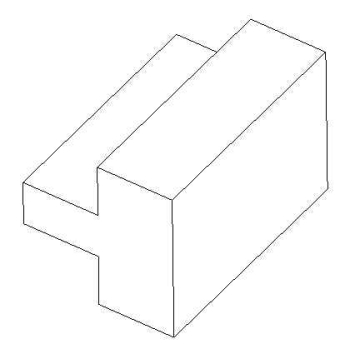
(Essay)
4.8/5 (32)
The number of orthographic views that you should draw to represent an object
(Multiple Choice)
4.9/5 (42)
The lines that provide information on the size of the object; for example, how wide it is and how long it is are known as
(Multiple Choice)
4.8/5 (39)
A machinist must be able to make the part from the detailed drawings without needing to go back to the engineer or the draftsperson who drew the drawings to ask questions regarding the size, or the tolerances, or what type of material the part should be made from.
(True/False)
4.8/5 (43)
An engineering drawing provides information, such as the shape of a product, its dimensions, materials from which to fabricate the product, and assembly steps.
(True/False)
4.8/5 (37)
The view that shows the solid portions and the voids within the object are known as
(Multiple Choice)
4.8/5 (40)
Engineers use technical drawings to convey useful information to others in a standard manner.
(True/False)
4.8/5 (38)
Filters
- Essay(0)
- Multiple Choice(0)
- Short Answer(0)
- True False(0)
- Matching(0)