Exam 1: Multimedia Authoring, Tools, Graphics and Image Data Representations
Ordered versus nonordered dithering.
(a) For a 2 dither matrix, write a pseudocode solution for the problem of producing a 1-bit ordereddither image from an input grayscale 8-bit image.
matlab version:
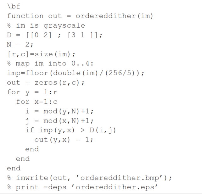 Output is as in Fig. 3.2.
Generally, for gray input images what are half-toning and dithering? How are they related to each other? What is ordered dithering?
Half-toning is analog method of printing larger-radius "dots" to show darker image regions. Dithering attempts to mimic this for 1-bit printer pixels by replacing each pixel by an array of 1-bit values, more matrix elements filled for darker image pixels. Ordered dithering replaces each grayscale pixel by bit=1 values, in the pattern dictated by the non-ordered dithering's dithering matrix.
For the same simple median-cut algorithm mentioned, suppose we decide to find medians in the order to make a 4-bit version of color. Thus for R, if we decide that a pixel's red value is less than the median, we proceed down the left branch of a binary tree and look at the green pixel values just for those left pixels, etc. So far, our best value for is the median for all red values.
So in the end, for our 4-bit color we have 16 bottom medians that are used, medians, and medians. Hence a question: do we not actually have 4 bits for R, 3 bits for , and 2 bits for , making 9-bit accuracy?
To answer this question, it may help to make a list of the sixteen 4-bit codes and the 24-bit color values we use to make up the color LUT - there are indeed only paths through the tree, and hence only 4-bit color. The 24-bit color in the LUT is comprised of the bottom-most medians we find in making the tree. And only the binary-tree paths through the tree are available, so we cannot really have all 16 possible bottom values, notwithstanding the fact that we have calculated 16 medians for .
Describe in detail, using pseudocode, how to use a single 8-bit image and a colour lookup table to realize a simple animation - a rotating colour wheel, in which a sequence of 8 snapshots will appear repetitively. (The wheel rotates counterclockwise each time; the first three snapshots are shown below: C - Cyan, M - Magenta, Y - Yellow, R - Red.) [You do not have to show how to explicitly assign pixels to quarter-circle segments.]
![Describe in detail, using pseudocode, how to use a single 8-bit image and a colour lookup table to realize a simple animation - a rotating colour wheel, in which a sequence of 8 snapshots will appear repetitively. (The wheel rotates 45^{\circ} counterclockwise each time; the first three snapshots are shown below: C - Cyan, M - Magenta, Y - Yellow, R - Red.) [You do not have to show how to explicitly assign pixels to quarter-circle segments.]](https://storage.examlex.com/TB10096/11ee8945_81c9_3520_949f_f7a8923e74a9_TB10096_00.jpg)
We know that the GIF standard can request a different number of bits than the number stored in the actual raster data in the file. Suppose that an output device allows only a few bits for color resolution (a wristwatch web-enabled wireless device, for example).
(a) How should our output device deal with the higher color resolution color LUT codes it receives? (Note that exactly this situation is in the GIF standard.)
(b) Suppose that the output device cannot display 24-bit color. To make sensible color output, how should the 24-bit colors in the color LUT be handled for output on a display with lower color resolution than 24-bit?
A simple (image independent) way of converting a full-color (24-bit color) RGB image into an 8-bit color (GIF) image is to allocate, e.g., 3 bits each to and , and 2 bits to . This results in poor quality of color, since you'll always only have 8 levels for R, G, and 4 levels for B, respectively.
Describe in sufficient detail an image dependent color conversion algorithm that will take into account of color content of the image so as to yield better 8-bit color (GIF) images.
When we create a sprite, we usually completely replace pixel values by those in the sprite. Suppose, however, we wish to replace pixel values by a combination with weights from the original background, plus from the sprite, where is in .
State how you could do this, using only LOGICAL operators and an ADD.
Assume you already have a sprite which has the character's colors all multiplied by the factor , and black outside the character;
and also suppose you already have a second image of the (entire) background, already multiplied by , called .
For the same problem, write a pseudocode solution for the equivalent problem using non-ordered dithering.
Dissolve: Suppose we have video1 dissolving into video2, over a time from 0 to (video1 gradually disappears, and video2 gradually appears).
There are 2 ways that this task is commonly carried out: "Ordinary Dissolve" and "Dither Dissolve". In Ordinary Dissolve, every pixel value is changed, over time, so that it contains partly the contents of video1 and partly the contents of video2, summed additively. In Dither Dissolve, pixels are either all-video1 or all-video2, not a mix; the decision of which video to take pixel values from is based on a random number generator.
Write pseudocode solutions for accomplishing these two kinds of gradual video transition. For each type, just show the algorithm for filling up R (Red) values - Green and Blue will be similar.
How would you create your own video wipe transition from the top-left corner of the viewport down to the bottom-right corner - a diagonal transition? Fig. 2.1 shows such a video transition.
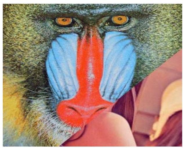 Fig. 2.1: Wipe transition, at
Here, we wish to simply take pixels from either the first or the second video, depending on whether they are above or below the moving diagonal line.
Write some pseudo-C or pseudo-Premiere pseudocode to produce correct pixel values during the transition.
Hint: for any x and y position, we can determine where the line that {x, y} is on, which is parallel to the wipe, cuts the main diagonal from top-left to bottom-right of the frame, simply using similar triangles. To do so, it's easiest to calculate the y-intersept of that line (where it hits the y-axis).
Fig. 2.1: Wipe transition, at
Here, we wish to simply take pixels from either the first or the second video, depending on whether they are above or below the moving diagonal line.
Write some pseudo-C or pseudo-Premiere pseudocode to produce correct pixel values during the transition.
Hint: for any x and y position, we can determine where the line that {x, y} is on, which is parallel to the wipe, cuts the main diagonal from top-left to bottom-right of the frame, simply using similar triangles. To do so, it's easiest to calculate the y-intersept of that line (where it hits the y-axis).
Filters
- Essay(0)
- Multiple Choice(0)
- Short Answer(0)
- True False(0)
- Matching(0)