Multiple Choice
A galvanometer G has an internal resistance rg. An AMMETER is constructed by incorporating the galvanometer and an additional resistance Rs. Which one of the figures below is the most appropriate circuit diagram for the ammeter? 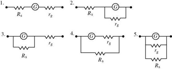
A) 1
B) 2
C) 3
D) 4
E) 5
Correct Answer:

Verified
Correct Answer:
Verified
Related Questions
Q5: A 5.0-Ω resistor and a 9.0-Ω resistor
Q14: A 4.0-μF capacitor that is initially uncharged
Q32: Two identical resistors of resistance R =
Q33: As more resistors are added in parallel
Q34: A galvanometer G has an internal resistance
Q35: Three resistors are connected across an ideal
Q37: An uncharged 1.0-μF capacitor is connected in
Q38: The figure shows three identical lightbulbs connected
Q40: For the circuit shown in the figure,
Q41: A multiloop circuit is shown in the